kbm10
Junior Member level 3
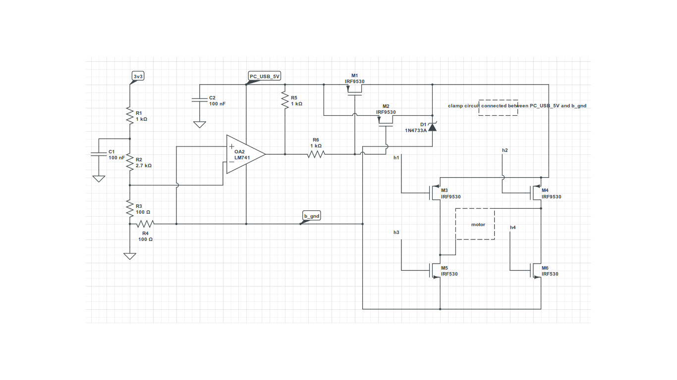
I have to drive motors using power drawn from USB port.
In order to limit the current drawn, I planning to desing a current limiting circuit. Can anyone pls share some current limit architectures ?
Also, wat sort of techniques are used to limit the initial current spike when motor starts...
Thnx in advance
In order to limit the current drawn, I planning to desing a current limiting circuit. Can anyone pls share some current limit architectures ?
Also, wat sort of techniques are used to limit the initial current spike when motor starts...
Thnx in advance
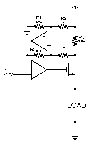
") It is a simple but effective way, but not as efficient as yours (presuming power dissipated by linear control is less than power consumed by Pwm control). It also solves the startup problem.
It is a simple but effective way, but not as efficient as yours (presuming power dissipated by linear control is less than power consumed by Pwm control). It also solves the startup problem.