Continue to Site

Welcome to EDAboard.com

Welcome to our site! EDAboard.com is an international Electronics Discussion Forum focused on EDA software, circuits, schematics, books, theory, papers, asic, pld, 8051, DSP, Network, RF, Analog Design, PCB, Service Manuals... and a whole lot more! To participate you need to register. Registration is free. Click here to register now.

measure bandwidth in HFSS

Status
Not open for further replies.

magsina

Newbie level 3
Joined
Apr 24, 2010
Messages
4
Helped
0
Reputation
0
Reaction score
0
Trophy points
1,281
Activity points
1,307
Hi everyone

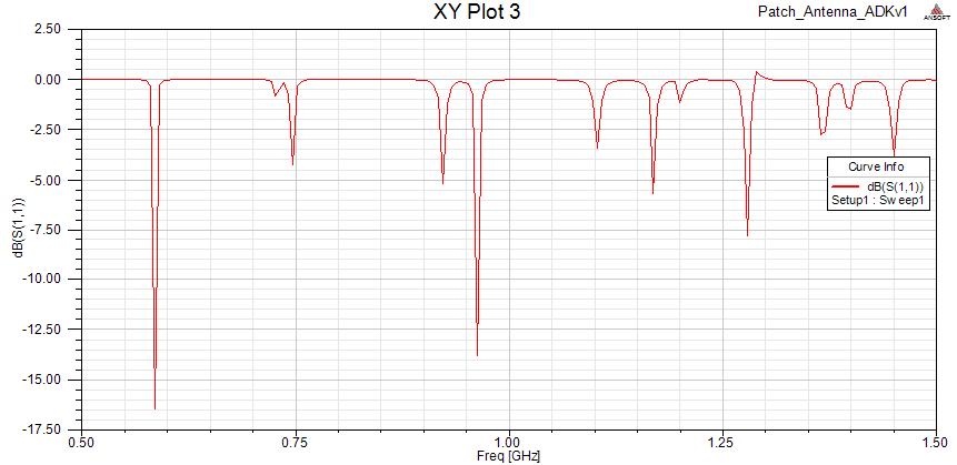
I designed a circular patch antenna using coax too feed it. I decided to measure its bandwidth using HFSS. so i used driven modal and plot the S11 curve. but the curve is really amazing! (i have attached it)

I have two questions:
1- is driven modal suitable to measure bandwidth
2- as i have understood we should use -10 db point to measure bandwidth. in fact the band between -10 db points is the bandwidth. am i right?

Thanks for helping me
 

hi
driven model suitable for antenna simulation
for Bandwidth we checked the antenna return loss less than -10 dB
 
hi
driven model suitable for antenna simulation
for Bandwidth we checked the antenna return loss less than -10 dB

thanks dear ferdows. but doesn't seem the curve which is attached wrong? (because it has sharp fluctuation.also in most frequencies s11 in 0db means that all the wave reflects!)

thanks
 
Last edited:

as you said u simulation a circular patch and this patch has less than 2% beamwidth at 3 GHz as i know so in your your simulation frequency it will be less than 2 % and so your simulation became too sharp and angular and it look first mode at less than 1 GHz
 
I have two questions:
1- is driven modal suitable to measure bandwidth
Yes
2- as i have understood we should use -10 db point to measure bandwidth. in fact the band between -10 db points is the bandwidth. am i right?

Thanks for helping me

Check the IEEE definition of bandwidth. I can't recall the exact wording, but basically the antenna's frequency response is that over which the antenna meets the critia you specify. So if you want to specify the 10 dB return loss points, then as long as you state that, you have defined the bandwidth. If you wanted it to define it as the freqency range over which you could apply 200 W of power without it melting, that would be ok. So you can basically define it how you want.

Personally, as a minimum, I'd like to see antennas frequency range being defined as that of which the gain is >= X dB and the return loss >= Y dB. But for many antennas, only the SWR/return loss is specified.

It's a fact of life, if you design an antenna for some freuquency (say 100 MHz), it is bound to have a very good return loss at some other freuqency well away. So any antenna will be "multi-band" to some extent if you only specify the return loss.

For many antennas sold commercially, I think the specifications are based on the "rand" button on someone's calculator. Many antennas don't meet the specs claimed of them.
 
Last edited:
thank you dear ferdows and dear debora! you really helped me
 

Status
Not open for further replies.

Part and Inventory Search

Welcome to EDABoard.com

Sponsor

Back
Top