KSHATRIYA
Member level 1
Hi all,
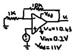
I want to design an amplifier which would amplify a sinusoidal signal from (0-300mV) at least 100 times. My frequency band is (10khz-1Mhz). Suppose my maximum input change would be around 20mV so I take a slew of around 2.3V/us. For choosing the right amplifier I see the frequency response curve of the amplifier and check whether in my operating frequency, will it be able to give me that gain. So I finally zeroed on OP27. I am using OP27 as a basic non-inverting amplifier (single one with a gain of 10) but I am unable to get any amplification rather I am getting the input DC Voltage with a little loss. I have not kept my resistor between Bal1 and Bal pins. Is my approach correct or I am missing something.
thank you for reading
Regards
Kshatriya