Continue to Site

Welcome to EDAboard.com

Welcome to our site! EDAboard.com is an international Electronics Discussion Forum focused on EDA software, circuits, schematics, books, theory, papers, asic, pld, 8051, DSP, Network, RF, Analog Design, PCB, Service Manuals... and a whole lot more! To participate you need to register. Registration is free. Click here to register now.

High voltage spikes on Forward converter's switch

Status
Not open for further replies.

loxly

Junior Member level 3
Joined
Mar 16, 2012
Messages
29
Helped
6
Reputation
12
Reaction score
6
Trophy points
1,283
Location
Zagreb, Croatia
Activity points
1,530
Hi everyone,

I had to design and construct flyback and forward converters for my Power Electronics course project. After testing and measurements the flyback converter is working like a charm, but I have some issues regarding my forward converter. :)

Here are some specs:

Input voltage 25V
Primary to secondary windings ratio 1:1
Primary to tertiary windings ratio 2:1
Duty cycle 0.5
Output inductor 1.2 mH
Output capacitor 690 uF
Output resistance 47 Ohm
Switc frequency 100 kHz

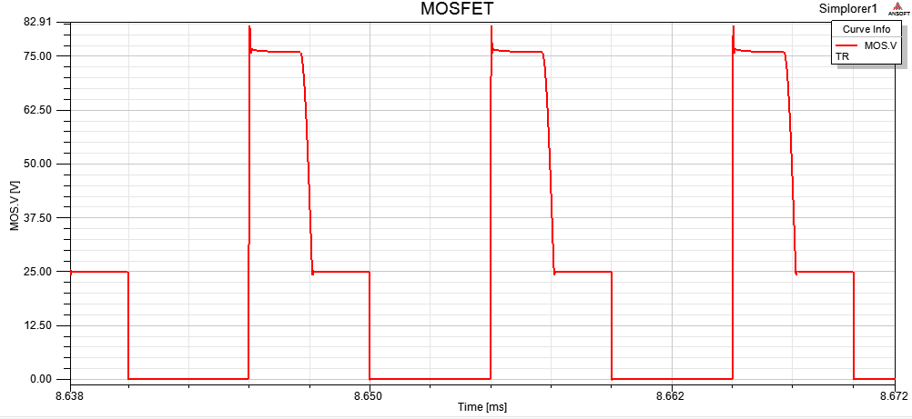
According to my calculations (and Simplorer simulations) MOSFET voltage waveform in stationary state should be:


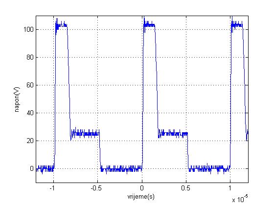
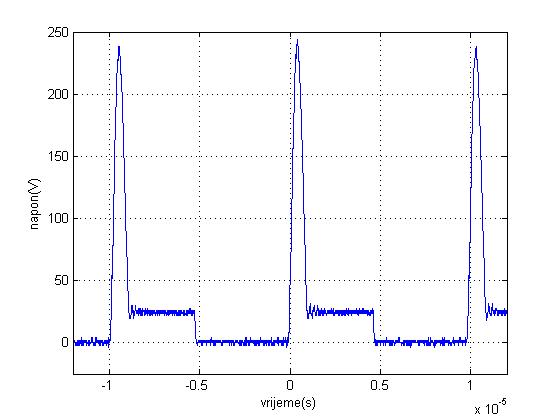
but instead, scope measurements showed this


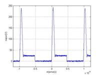
As you can see, the voltage spikes are definitely too high, and the thing is that spikes are getting higher as I'm raising duty cycle and lower as I'm lowering it. That shouldn't happen! Changing duty cycle should only vary spikes width, not the amplitude.

So I'm asking You, what could be the problem? :)

I ruled out some possible issues like not properly connected tertiary winding or inductor issues.

I'm suspecting the primary leakage inductance is too high. Transformer was wounded by hand. I don't have protective RCD circuit cause I thought I wouldn't need one :) (and most of them don't have it in practice as I have seen)

Please help

Thank you in advance :)

Lovro
 

  • Like
Reactions: loxly

    loxly

    Points: 2
    Helpful Answer Positive Rating
Thank you for your reply :)

I know, what's the snubber, I used it on my flyback transformer and it's working like a charm :)

I just though I wouldn't need one on my forward converter.

Am I right about high leakage inductance causing the spikes?
 

Maybe, but it`s hard to explain, because if you wonded the transformer good, with good phasing between windings it will work good, but if you have a bad wonded transformer, may be problems.
 
  • Like
Reactions: loxly

    loxly

    Points: 2
    Helpful Answer Positive Rating
Of course, I understand.

The transformer was wounded by our laborer by hand so that could likely be the problem.

I'll try to add RCD snubber in parallel with primary winding (the same as for flyback) and see what will happen
 

I have RCD snubber fo flyback (D in series wit RC parallel (R=8k, C=47nF)). The biggest problem is time, I have my diploma thesis defense on Friday :)

...so I will first try with what I have. If that wouldn't work, I'll try with RC :)
 

Dear loxly
Hi
I think the problem is not for snubber ! can you tell me how many is the number of turns for your primary and how much for reset coil ? ( i think you are using single ended forward converter , right ?)
Best Wishes
Goldsmith
 
  • Like
Reactions: loxly

    loxly

    Points: 2
    Helpful Answer Positive Rating
Hi Goldsmith!

I'm using 32 turns for primary and secondary and 16 turns for reset winding. PExprt calculations showed everything was ok
I'm using single ended I guess :)

I'm still hoping it's snubber cause it's easier to modify, but you're the expert :)
 

Hi again
I suspected to this ! there are three conditions : 1-npri>nreset 2- npri=nreset 3- npri<nreset . you have done first one ! thus the core can't be empty from magnetic fluxes , as soon as enough . hence if you select mode 2 or three the spikes will remove as well ! if primary is 32 turns , wind 33 or 36 turn for reset winding .
Best Wishes and Good luck
Goldsmith
 
  • Like
Reactions: loxly

    loxly

    Points: 2
    Helpful Answer Positive Rating
If I wind 32 turns on my tertiary winding, then the maximum (allowed) duty cycle is 0.5, right?

Can you please give me more detailed explanation why should I try with more turns on tertiary winding?
I've read about some examples where P:T was also 2:1, but I've never heard about that problem. Of course, theory and practice are two different things.

I'm afraid my transformers core halves are clamped together and placed on PCB, and I'm not sure I can open it. In addition, I think there wont be place for any more turns, so it will be very impractical.

Do you think maybe adding snubber will still solve the problem?

Thanks for helping me!
 

Hi,

From the waveform of the MOSFET, I find the reset time is too short.
So I also think the problem is not for the snubber ,and it's a transformer reset problem.
in my opinion adding a snubber can not improve the spike voltage. I suggest you increase the primary inductance 。
If the inductance factor is 2500nH/N2 ,the primary inductance is about 2.5mH.
 
  • Like
Reactions: loxly

    loxly

    Points: 2
    Helpful Answer Positive Rating
I ruled out some possible issues like not properly connected tertiary winding or inductor issues.
How did you? I also wonder if the secondary winding + rectifier are connected correctly. The waveform can't be related to a regularly operating forward converter, I think. It's definitely not the time to think about snubbers, you should analyze the observed circuit behaviour and the faults that are causing it. Showing the waveforms at the secondary and "tertiary" (reset) windings can help.

It would be probably better to see a schematic, otherwise there's a risk to jump into conclusions about the actual circuit.
 
  • Like
Reactions: loxly

    loxly

    Points: 2
    Helpful Answer Positive Rating
suggest to reduce leakage inductance about primary winding, change winding method
 
  • Like
Reactions: loxly

    loxly

    Points: 2
    Helpful Answer Positive Rating
Hi loxly
I think these pages can help you as well :
IMG_10523.jpg
Best Wishes
Goldsmith
 
Thank you everyone for your help! Sorry I wasn't here these days, I was very busy.

In the meantime I've tried adding snubber and it helped reducing voltage spikes. Now the spikes are about 100 V. I don't think that solved the problem because the MOS waveforms still don't match the regular forward converter....so snubber just lower spikes, not solving the problem...

I'm not sure if I will have any more time to try anything else.

here's the MOS voltage waveform now btw :)


Hi loxly
Did you see those pages that i have attached in my latest post ? did you understand them ? if yes , why you didn't improve your reset windings ? i told you it is the only reason !
 

I just wanted to ask you one more question!

About the forward converter compensator.
I constructed and tested voltage mode controller for buck converter and it was working very good.

The parameters of forward converter are the same (same L,C, R and turns ratio is 1), so I tested it on forward converter too.

The response was also OK, although it was a bit slower, but I guess that's logical because the transformer is degrading dynamics.

The question is: Is it ok to use the same compensator for forward and buck? :)

Variable load was used as disturbance btw.

- - - Updated - - -

Hi Goldsmith,

I would definitely try to do as you told but I'm afraid I wouldn't have time for that right now :(

I understand how increasing reset turns may help reducing spikes, but I still don't get why should P:T=2:1 turns ratio be a problem. In that case if voltage source is 25 V, maximum voltage on MOS should be 75 V (ideal), during reset time. I understand the theory and understand what you've posted
 

I don't understand which problems you mean to recognize in the waveform of post #16. It's a perfect converter waveform, only different from the simulated waveform in post #1 by a larger windings ratio. If the waveformis different from your expectations, I guess you hav ea problem in transformer calculation.
 
  • Like
Reactions: loxly

    loxly

    Points: 2
    Helpful Answer Positive Rating
Status
Not open for further replies.

Similar threads

Part and Inventory Search

Welcome to EDABoard.com

Sponsor

Back
Top