Continue to Site

Welcome to EDAboard.com

Welcome to our site! EDAboard.com is an international Electronics Discussion Forum focused on EDA software, circuits, schematics, books, theory, papers, asic, pld, 8051, DSP, Network, RF, Analog Design, PCB, Service Manuals... and a whole lot more! To participate you need to register. Registration is free. Click here to register now.

Inductor and transformer design methodology!

Status
Not open for further replies.
can anyone tell me how to make auxiliary supply in case of input of 220VAC......
im going to make a charger of high current. kindly tell me how i manage to use aux supply with minimum loss

Thanks
 

Dear Muhammad
Hi
Of course i can help you , but but with what specification ? to self supplying your circuit ? or another aim ? if you tell me a bit more explanations i can help you .
Best Wishes
Goldsmith
 

Hello there goldsmith and others,

I saw a tutorial on how to design and build a iron core transformer, and I must say that it was very helpful and I could understand how the thing works.

But some questions arose in my mind.

First, the configuration of the core was EI and the guy that did that tutorial used the center of the core to build the transformer. I saw other types of configuration, like for example, a picture of a transformer where the coils were at the each side of the core. My first question is: What kind of differences exists in such configurations?

Now that I've understand how to design the transformer (iron core), I still don't understand how to design a HF transformer. The theory is the same? I ask that because the core is different: HF Transformer - Ferrite core. Normal transformer: Iron core.

BTW, about the coils to use for example in a buck, boost converter, what kind of material are made the core?
 

Humm . at first Hi my friend !
And about cores : we have many many types of core . such as M or MI or EE or EI or L or H or T or TI or toroidal cores ! or ... etc
The purpose of core is to carry the magnetic forces . some limitations will allow you to select your desired core . such as price or shape of core ( because sometimes you don't have enough distance to put your transformer ( for example in Y axis or X axis) . but in fact all of them are the same ! . )
and about HF transformers and inductors , did you read the literatures that i have attached in this thread ?
Best wishes
Goldsmith
 

Hi goldsmith!

Yes I've read that. There are some doubts but, even so, what I can't understand is, when I look at one book of Electrical Machines, where this subject is mentioned, even though for 50Hz, there are some formulas that are a little more complicated than those that you're using in you application notes. There is too an equivalent circuit for the transformer as well as formulas for the losses, etc.

For example, in the lectures notes from prof.º Eriksson from Colorado University - you can see here: **broken link removed**, he has lot's of complicated formulas and theory that he uses to design the transformer that you don't get into account in your appl. note. Do you understand what I mean?

For example, in the 3rd slide, there is a formula to compute the core loss. How can I calculate that losses with you application note? I read somewhere that we need to take in account with the window area (or whatever it is), and other aspects (that I don't remember now). You don't mention that in you app. note. Do you understand? I'm not talking bad about your app. note, (and I believe that it works for sure because you seen to be a very expert guy in this subjects ;) ) but instead, I'm talking about some doubts that arose from looking into your note.

By the way, how we wrap the copper wire around the core? We need some kind of plastic support (like those conventional transformers for 50Hz)?

Another question, I read too (don't remember where) that the core of this kind of transformer have more induction than the conventional transformers, something like 10000 more! I am note sure of that, I think I read that somewhere. Is that true? But for ferrite?

Last question: what kind of core are those in the inductors, for example, in SMPS?

Bes regards and THANK you very MUCH!
 

Yes I've read that. There are some doubts but, even so, what I can't understand is, when I look at one book of Electrical Machines, where this subject is mentioned, even though for 50Hz, there are some formulas that are a little more complicated than those that you're using
Hi again
Is each complicated thing better than simpler things in your idea ? if yes , why you use spoon to eat food ? of course spoon is for simplification ( at first ) ( and at second for safety from diseases ) . isn't eat ? all of humans want to simplify each thing for better living . i used my formulas for many times . in many of my transmitters and smps circuits . all of them were fine ! however in pretty high or pretty low powers .
By the way, how we wrap the copper wire around the core
not around small size cores ! i have used a copper pipe for main heart of my combiners in my transmitters , and for big cores . however smaller size of copper pipes are available . but don't forget the aim of that pipe ! we have an interesting effect that called skin effect , that means the current in alternative currents don't want go through the center of wire . but at low frequencies it is inconsiderable . but at high frequencies , this effect will multiply! so at high frequencies the center of wire is useless . and we can use a pipe which has oil or water internally ( and a pump to control it's speed ) . these materials can decrease the temperature of our pipe . hence we can use some pipes in parallel for higher powers ( e.g 500KW ) .
Anywhere , i don't think that you want hear about high frequencies !
And about core loss or copper loss , most of the times because of low value of dissipation in core and wire we can neglect from them unless high powers and high frequencies . in those cases there are many simpler ways available too . ( i have my own ways to design each thing ! because i don't want waste my time for some days to calculate a simple thing ! )
For example if you don't want predict loss before build , you can measure it in practice simply , but if you want consider it in your design process , you can consider , just 5 percent or a bit higher ! ( there are many complicated ways available too , i know about many of them , such as calculations of iron core transformers , but these days , i won't use those time consuming ways , because there is no needed to dissipating the time ! )
And a few notes about core : if i don't have limitation in size ( y axis or x axis ) i will use PQ series or EE series . but if i have limitation i will use FM series cores ( e.g FM36 or FM63 or for higher powers some of them in parallel ).
If you have any problem , bring an example , and we can design it together , and be sure that i will help you , as much as i can .
Nice times
Goldsmith ;-)
 

Hi my friends
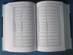
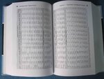
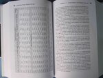
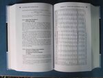
Sorry because of created delay , at last i have attached the tables for selecting best core in your designs !
See below , please :
IMG_0990.jpg
IMG_0991.jpg
IMG_0992.jpg
IMG_0993.jpg
I hope these tables can be helpful for all of you ! if you want , i have many many tables that i can attach for all kind of ferrite cores ! ( however you can use these cores for powers up to 1MW or higher !! ( don't confuse ! , you can use each core in parallel to the other cores to achieve higher permeability and higher powers ! )
Good luck
Goldsmith
 
Here I'm attaching pdf version of the power table
 

Attachments

  • MaximumAvailableOutputPower.pdf
    82.8 KB · Views: 449
Dear Sam
Hi
Thank you because that you changed it into PDF . it will help , many of the peoples , that have problem to load those pictures . :wink:
Best Regards and best wishes
Goldsmith


Hi dear saeid
You can't find that in any reference ! i made that table with large value of experiments ! . although there are some books that talked about variation in frequency and density of current . but i preferred to simplify design steps thus every one can use this way simply without any complicated calculations .
Good luck
Goldsmith
 
Hi Mr.goldsmith
According to your papers I try to design 40watt switching transformer with forward topology. In attach file you can see all specifications. But I have three question:

1. Dose it my transformer equations is right? What percentage is to work well?
2. In your papers you don't use flux density! Why? Dose not important or you have another reason?
3. I use PQ3220 core, but I don't know what the material is made? How can I know core material?

Good Luck :)
 

Attachments

  • Forward Transformer Equations.pdf
    48.9 KB · Views: 244

Theory design is only beginning, practice is more importance, when we design a magnetics parts, we not only meet customer requirement, but also we can make mass products, can consider quality question when the part are made mass products.
 

Hi Mr.goldsmith
According to your papers I try to design 40watt switching transformer with forward topology. In attach file you can see all specifications. But I have three question:

1. Dose it my transformer equations is right? What percentage is to work well?
2. In your papers you don't use flux density! Why? Dose not important or you have another reason?
3. I use PQ3220 core, but I don't know what the material is made? How can I know core material?

Good Luck :)
Hi Saeid
Before trying to answer your questions here , i should improve your calculations :
you need 40 volts in out put . but i hope you know maximum allowed duty cycle for a forward converter is something around 50 percent . hence if you design it for 40 volts out put , after your out put filter , you'll have 20 volts with maximum duty cycle and when you put the load in your out puts , you'll see that your out put voltage is going to be lower !!
Hence you should design it as : 100 volts in your out put ! then after your filter you'll have something around 50 volts ! and then you'll have 10 volts for compensation ! ( loading compensation ) .
I hope you get the point !
And about your input voltage ( your specification tells that is between 110 and 230 ) hence i hope you know when you give it 110 volts , thus in out put you'll have lower voltage . if you want your circuit be able to compensate this effect and deliver your required voltage in out put , you have to consider this input in your design too and then you'll ned more than 100 volts in out put .

By the way , may i ask you why you've selected 75KHZ as PWM frequency ? why not higher ? ( is your forward converter , a current mode forward converter ? or perhaps that is a voltage mode ?)
my suggestion is something around 150 KHZ .
1. Dose it my transformer equations is right? What percentage is to work well?
Can you clarify your meaning , please ?
2. In your papers you don't use flux density! Why? Dose not important or you have another reason?
Yes we've used it ! but not directly ! the LCR meter did it's best ! it means when you're using an LCR meter , you won't need to use such parameters in your design steps .
3. I use PQ3220 core, but I don't know what the material is made? How can I know core material?
You can refer to it's datasheet .
Best Wishes
Goldsmith
 
Last edited:
Thanks for reply Mr.Goldsmith and excuse me for my English

you need 40 volts in out put . but i hope you know maximum allowed duty cycle for a forward converter is something around 50 percent . hence if you design it for 40 volts out put , after your out put filter , you'll have 20 volts with maximum duty cycle and when you put the load in your out puts , you'll see that your out put voltage is going to be lower !!*
Hence you should design it as : 100 volts in your out put ! then after your filter you'll have something around 50 volts ! and then you'll have 10 volts for compensation ! ( loading compensation ) .*

I forgot that 100 volts applied to the calculation. I used below equation to calculating maximum voltage to secondary and I know in forward and flyback converter 10 percent of maximum duty cycle is dead time and available duty cycle is 40%

max secondary voltage: Vs = Vout/duty

And about your input voltage ( your specification tells that is between 110 and 230 ) hence i hope you know when you give it 110 volts , thus in out put you'll have lower voltage . if you want your circuit be able to compensate this effect and deliver your required voltage in out put , you have to consider this input in your design too and then you'll ned more than 100 volts in out put .*

Yes, I know, when input voltage is decrease, compensation network compensate output voltage with increase duty cycle.

By the way , may i ask you why you've selected 75KHZ as PWM frequency ? why not higher ? ( is your forward converter , a current mode forward converter ? or perhaps that is a voltage mode ?)my suggestion is something around 150 KHZ .**

Unfortunately when I design first smps circuit, I use 150khz but power dissipation on snubber network is very large!!! I don't know why my transformers spike voltage is very large!! I try to decrease leakage inductance below 12uH but can't solve problem!!! in below link you can see my problems and see schematic circuit
https://www.edaboard.com/threads/270064/#post1158250
The last word, I can't control power dissipation in all smps board

3. I use PQ3220 core, but I don't know what the material is made? How can I know core material?
You can refer to it's datasheet .

I know if I refer to data sheet can found material but I want know how can I practical define material cores with oscilloscope , signal generator or LCR meter?
 

Hi Saeid
Yes, I know, when input voltage is decrease, compensation network compensate output voltage with increase duty cycle.
Who told this ? do you know meaning behind the word compensation ? or loop stability ?
I know if I refer to data sheet can found material but I want know how can I practical define material cores with oscilloscope , signal generator or LCR meter?
Of course you can find it in practice too ! but it is a bit hard .
Unfortunately when I design first smps circuit, I use 150khz but power dissipation on snubber network is very large!!! I don't know why my transformers spike voltage is very large!! I try to decrease leakage inductance below 12uH but can't solve problem!!! in below link you can see my problems and see schematic circuit
Large Voltage Spike in Forward Converter at No LOAD!!
The last word, I can't control power dissipation in all smps board
I think now your problem is solved ? right ?
Best Wishes
Goldsmith
 
Status
Not open for further replies.

Similar threads

Part and Inventory Search

Welcome to EDABoard.com

Sponsor

Back
Top