Continue to Site

Welcome to EDAboard.com

Welcome to our site! EDAboard.com is an international Electronics Discussion Forum focused on EDA software, circuits, schematics, books, theory, papers, asic, pld, 8051, DSP, Network, RF, Analog Design, PCB, Service Manuals... and a whole lot more! To participate you need to register. Registration is free. Click here to register now.

Solid State 110 Volt timer delay circuit help

Status
Not open for further replies.
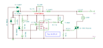
I use C2 for some simple EMI suppression.

---------- Post added at 00:23 ---------- Previous post was at 00:17 ----------

And the test results:

Not so bad this time, need to work to obtain more delay.
 
Please tell the configuration of 10uF Capacitor in the Voltage supply part ...i mean is it 10uf /63V or 10uf/...V

This one will work for sure:

**broken link removed**

EDIT: Opamp inputs will be reversed.
Vref ==> Inverting input
Vcharge ==> Non-inverting input
 

It has the full rectified mains voltage across it (more than 300V), so it should be an X or Y-rated capacitor.
 

Its a half wave rectified voltage ..i guess :)

It has the full rectified mains voltage across it (more than 300V), so it should be an X or Y-rated capacitor.

- - - Updated - - -

Can polarised capacitor of 10uf/63V will work here ..?/ please guide me which capacitor of X Y Capacitor .. i mean the configuration for the 220VAC supply
 

So? What’s the maximum voltage across it? :roll:

- - - Updated - - -

By the way, in that diagram we need to reverse the 30V zener diode….
 

yesch that thing i know ... the Zener will be reversed to act as constant voltage source ,,, i am using 15 v zener diode ... i need to operate 555 timer with that supply ...

so plzz guide me which capacitor i should use for 220 VAC .. also will this is supply is good to drive a 555 only ??
So? What’s the maximum voltage across it? :roll:

- - - Updated - - -

By the way, in that diagram we need to reverse the 30V zener diode….
 

could u help me .. i need to avoid the transformer ... i want the power supply of +5-10 VDc .... the issue with transformer is i want to minimise the power supply part as minimum as possible :)
No, you need to redesign the whole circuit…
 

Take extra care when you are working with live mains, any direct contact with power lines is dangerous and can cause serious injury.

- - - Updated - - -

What are the specs to design the circuit?
 

i need to drive a 555 timer .. which further drive Triac via Optocoupler .. so i need a Power converter from 220VAC to 5-10 Vdc ... and that too in minimum size ...:)


Take extra care when you are working with live mains, any direct contact with power lines is dangerous and can cause serious injury.

- - - Updated - - -

What are the specs to design the circuit?
 

If you don’t use a separation transformer, you don’t need for the optocoupler. See the attached diagram.
 

Attachments

  • Turn ON delay.png
    Turn ON delay.png
    65.9 KB · Views: 101
Common working DC voltages for C1, C4 are 16V, 25V, 35V… :)
C3 =100nF rated usually 50V/63V
The critical part C2, that’s a line filter capacitor, 'X Caps' usually connected across the AC supply, and must be of special construction so they do not fail and or become a fire or electrocution safety hazard.
Usually rated for minimum 250Vac (275Vac/300Vac/400Vac)

e.g.

**broken link removed**

545ae548-39f6-46ca-9f41-19af855ea05f_X1.jpg


safety_kinds_of_capacitor.jpg
 
Status
Not open for further replies.

Part and Inventory Search

Welcome to EDABoard.com

Sponsor

Back
Top