mkelly09
Newbie level 6
Hello, I am attempting to build a linear voltage regulated power supply with the following requirements:
-3 outputs:
I have the following design that only does the first variable output, and I think this part of the design is pretty solid:

https://i.imgur.com/N53PD.png
-Note that the second switch off the secondary of the transformer is basically used to control heat dissipation in the LM317. I will hit the switch when I need high current at low voltage to reduce the voltage drop across the regulator.
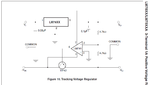
I'm wondering how I could modify this to include + / - supplies for powering op-amps. I want to be able to adjust them from say 15V up to 22V, and I want them to be tracked (adjust them both with 1 pot)
Would a second transformer be the best (easiest) solution?
-3 outputs:
- 1 Variable 0-30Volts output up to 1A
- + / - matched (tracked) output for powering various op-amps (up to 22V for ua741)
I have the following design that only does the first variable output, and I think this part of the design is pretty solid:
https://i.imgur.com/N53PD.png
-Note that the second switch off the secondary of the transformer is basically used to control heat dissipation in the LM317. I will hit the switch when I need high current at low voltage to reduce the voltage drop across the regulator.
I'm wondering how I could modify this to include + / - supplies for powering op-amps. I want to be able to adjust them from say 15V up to 22V, and I want them to be tracked (adjust them both with 1 pot)
Would a second transformer be the best (easiest) solution?