Continue to Site

Welcome to EDAboard.com

Welcome to our site! EDAboard.com is an international Electronics Discussion Forum focused on EDA software, circuits, schematics, books, theory, papers, asic, pld, 8051, DSP, Network, RF, Analog Design, PCB, Service Manuals... and a whole lot more! To participate you need to register. Registration is free. Click here to register now.

4xPIC16F877A to PC Communication

Status
Not open for further replies.

nooobboy4321

Junior Member level 1
Joined
May 22, 2012
Messages
18
Helped
0
Reputation
0
Reaction score
0
Trophy points
1,281
Activity points
1,447
Hello Guys,
I'm new in the world of microcontroller. I have this thesis proposal that needs to use a couple of microcontroller connected to a PC.
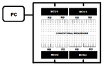
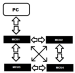
Here's my simple diagram of my idea on how the connection look like. My question is, is it possible to do that? Knowing that a PIC16F877A has only a pair of RX/TX Pin?

Thanks.
 

Attachments

  • MCUD.png
    MCUD.png
    12 KB · Views: 80
Last edited:

no with single UART pair you cant connect two device its not possible. Can you just brief us with your application or what you want to do ?
 
I'm building a Protoboard. My Protoboard is consist of mainly a BreadBoard and some Input Switch and Output Indicator. My goal is to emulate and simulate a given circuit that a USER creates on my BreadBoard. The BreadBoard is connected to a MCU and to PC.

Thanks for the quick response ud23
 

If you want connect that, you need 1 to be a Master (PC) and 4 PIC to be Slave. But, you can't connect through simple UART. You need to change UART signal into RS485 signal and protocol to communicate that ex Modbus.

RS232 can't because can't connect multi-point, RS485 can connect multi-point.
 
My goal is to emulate and simulate a given circuit that a USER creates on my BreadBoard.

which circuit you are talking about?what do you want to do with specially PC with MCU and how many slave in your circuit?
 

Thanks again ud23...My Thesis proposal is like a teacher of basic Logic Gates, it means the USER can Build a basic Logic Circuit using the conventional gates AND Gate (74LS08) and OR Gate (74LS32) into my Protoboard where my Breadboard is located. If the USER then builds a Gate, For example the user Puts a OR gate and creates A+B..... a software will determine what kind of IC the user use and the coordinates of the IC where the USER insert the 14 Pin IC. Here is my theory... can you check it?
 

Attachments

  • breadboard.png
    breadboard.png
    15 KB · Views: 88

Hello engshahrul,
Can you explain to me that concept that you said a little more simple? About that RS485? What kind of IC is that?

Thanks alot.
 

RS485 is a protocol not an IC, it allows serial communication between several devices along a two wires. It relies on devices being able to connect or disconnect themselves from the wires in order to avoid a data collision.

It is actually possible to do it the way you suggested in the first post but it is very tricky, you have to use the TRIS registers in the PIC rather than the port drivers to control the connecting wires. I have done it in the past but it took a long time to get it right and the solution I used may not be applicable in your case. you wire everything together in a "wired-OR" configuration and use the TRIS register to pull the lines low, the logic high is produced by pull-up resistors alone, nothing ever drives the lines high. Not for the feint hearted!

Brian.
 
Hello Brian,
What do you mean by "use the TRIS Registers in the PIC rather than the Port Drivers to control the connecting wires"
and the "wired-OR"? Did you the second attachment that I show? Is it Possible?

About the post earlier about RS485, can I use that type of protocol in my project?

Thanks alot Brian.
 

About the post earlier about RS485, can I use that type of protocol in my project?

Yes, if you understand Modbus you can create own protocol for communicating master and slave because you are designing both part.
 
Hello engshahrul, its confusing for me because I don't have enough knowledge about that topic but thanks for the advice.
 

I'm not going to write software for you, I've got too much of it to do already!

This is the principle though:

1. understand that one transmitter (TX pin or data from the PC) can drive many RX pins connected together. RX pins are inputs so they would all receive the same data.
2. understand that ONLY ONE TX signal can be active at any time. These are outputs so if two were connected at the same time the data would corrupt and if one TX pin was high while another was low, current would flow between them and damage the PIC.
3. understand that if a PIC pin is driven low (zero) but it's corresponding TRIS bit is set high (pin is an input) it can not sink any current.

So what you do is join all the TX and RX pins together but make the TRIS bit on the data outputs (TX) pin =1 so nothing is driving them. Add a pull-up resistor (1K) so the connection is high when nothing is being transmitted. At this stage none of the TX pins are sourcing or sinking current and all the RX pins are high because they are being pulled up by the resistor.

To transmit data, the TX pin is driven low (it stays low permanently) and the bits you want to send are put in the TRIS register bit for that pin. When the bit is zero, the pin becomes an output and because it is driven low, the data line goes low, when you put a '1' in the TRIS bit, the pin becomes an input, no current is drawn and the resistor pulls the data line high. So the TRIS bit is used instead of the TX bit. Because you are never drive the data line high, the current is limited to a safe level by the resistor.

That gets the data around all the PICs, but as they are all in parallel you need a method to route data to the correct one. This is where software comes to the rescue. You have to invent a protocol, it is entirely up to you how you do it. Each byte or block of bytes has to have an identifier (packet address) assigned to it. As all the PICs and the PC receive data in parallel, they all see the same data and have to look at the address to see if the data is for themselves or for another. They should only respond to data matching their own address and they should ignore anything else. At it's simplest, all you might do is prefix each block of data with an ID byte, for example if you sent "4Hello", PIC 4 would recognize it's ID and respond, sending "2World" would make PIC 2 respond.

Brian.
 
Thanks again Brian, I will study your principle and try to execute it correctly.
 

Status
Not open for further replies.

Similar threads

Part and Inventory Search

Welcome to EDABoard.com

Sponsor

Back
Top