Continue to Site

Welcome to EDAboard.com

Welcome to our site! EDAboard.com is an international Electronics Discussion Forum focused on EDA software, circuits, schematics, books, theory, papers, asic, pld, 8051, DSP, Network, RF, Analog Design, PCB, Service Manuals... and a whole lot more! To participate you need to register. Registration is free. Click here to register now.

TTL pulse generator with adjustable Rise and Fall

Status
Not open for further replies.

djnik1362

Full Member level 2
Joined
Aug 9, 2010
Messages
136
Helped
1
Reputation
2
Reaction score
1
Trophy points
1,298
Location
IRAN
Activity points
2,374
hi
How can i design a TTL pulse generator with adjustable Rise and Fall ?
Output power can be about 100 mW .

Can i use a high speed D2A ?

Thanks for your support.
 

Dear djnik1362
Hi
It is simple , try to use an RCD network and 3 schmitt trigger not gate . but you forgot to mention that how much is the range of your frequency ?!
And about power , you can add two simple transistor to achieve it .
Best Wishes
Goldsmith
 
frequency is about 200 KHz.
With using your idea i can't adjust rise and fall in real-time manner .
I must change rise and fall from software in real-time.

---------- Post added at 15:53 ---------- Previous post was at 15:52 ----------

frequency is about 200 KHz.
With using your idea i can't adjust rise and fall in real-time manner .
I must change rise and fall from software in real-time.
 

frequency is about 200 KHz.
Next time you'll mention rise and fall times?

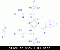
Classical analog pulse generators with variable rise and fall times are using switched programmable current sources, an integrating capacitor and a clamp circuit to define the high and low level.

---------- Post added at 17:58 ---------- Previous post was at 17:51 ----------

A principle schematic can look like below:

 
With using your idea i can't adjust rise and fall in real-time manner .
I must change rise and fall from software in real-time.
Hi again
What do you mean by that ? it is a usual way to do it . however the circuit that FvM attached is very incredible for your aim .
Best Lucks
Goldsmith
 
It's to simple. you can use an RC circuit with an buffered opamp at the output of your Fast TTL Circuit. If you want to control from software you can use an adjustable resistance or may be pump circuit.
Another approch is an simple DAC with an FPGA triangle wave generator. It is very easy to control but a little difficult to implement in HDL language. If you want this approach i can help you to implement on a small cheap CPLD!!!
 
It's to simple. you can use an RC circuit with an buffered opamp at the output of your Fast TTL Circuit. If you want to control from software you can use an adjustable resistance or may be pump circuit.
If you can accept exponential first order response as adjustable rise and fall time, yes. The electronical variable resistance point is still not so easy.

Another approch is an simple DAC with an FPGA triangle wave generator. It is very easy to control but a little difficult to implement in HDL language. If you want this approach i can help you to implement on a small cheap CPLD!!!
Depends on the intended rise time. You need at least 5 samples per ramp time and a good filter (e.g. 3rd order gaussian) to get an acceptable ramp waveform.
 
I plan at lest 64 (6bit) sample with cheap resistance DAC network and a small buffered opamp. It doesn't need the filter or just a cap. You can simulate the output using HDL. I have made a resistance DAC (for only DAC not like your case) and it is working fine. We can try it. But base on my experience it will works fine.

Another approach is a pump circuit and a programmable current source. It again needs the buffered opamp. but the circuit is difficult.
 
Last edited:
Next time you'll mention rise and fall times?

Classical analog pulse generators with variable rise and fall times are using switched programmable current sources, an integrating capacitor and a clamp circuit to define the high and low level.

---------- Post added at 17:58 ---------- Previous post was at 17:51 ----------

A principle schematic can look like below:


Thanks . very helpful.

---------- Post added at 15:46 ---------- Previous post was at 15:43 ----------

I plan at lest 64 (6bit) sample with cheap resistance DAC network and a small buffered opamp. It doesn't need the filter or just a cap. You can simulate the output using HDL. I have made a resistance DAC (for only DAC not like your case) and it is working fine. We can try it. But base on my experience it will works fine.

Another approach is a pump circuit and a programmable current source. It again needs the buffered opamp. but the circuit is difficult.

i need rise and fall be adjusted by 25ns resolution.
I think using DAC approach in my situation will be right choice.
Thanks.
 

Depends on the intended rise time. You need at least 5 samples per ramp time and a good filter (e.g. 3rd order gaussian) to get an acceptable ramp waveform.

I'm interested in this as well. I apologize for being a bit caustic, but how would this work. So you would send 5 or so digital sample points to the DAC and then use a digital or analog gaussian filter to "fill in" the rest of the area between the sample points, like an interpolation/reconstruction filter or some some kind of up-sampling (is this correct)? Also, why a Gaussian filter?
 
Last edited:

My Idea:

Using XC9572 and 160 MHz Crystal Oscillator and giving about 6 ns resolution.
 

but how would this work. So you would send 5 or so digital sample points to the DAC and then use a digital or analog gaussian filter to "fill in" the rest of the area between the sample points, like an interpolation/reconstruction filter or some some kind of up-sampling (is this correct)? Also, why a Gaussian filter?
A reconstruction filter is essentially a low pass. Because you want a time domain response without overshoot, you need to select a respective low Q filter, Bessel or Gaussian.

Ultimately, the generator will produce a monotonic output signal even for a single input step.
 

A reconstruction filter is essentially a low pass. Because you want a time domain response without overshoot, you need to select a respective low Q filter, Bessel or Gaussian.

Ultimately, the generator will produce a monotonic output signal even for a single input step.

I think I follow now, a low pass would be a poor choice because it could produce overshoot and ringing between samples.. correct? Are there any configurable IC's that could do the filtering for me or would this be best designed from scratch using op-amps? I wonder if this could be useful in something like analog video for the deflection signals? The CPLD/FPGA would offer quite a bit of configurability to the design.
 

a low pass would be a poor choice because it could produce overshoot and ringing between samples.. correct?
Not necessarily, it's a matter of low pass characteristics. Most today's universal function generators are using DAC with reconstruction filter.
 

I think a low pass 10 nf cap is enough.
 

Status
Not open for further replies.

Part and Inventory Search

Welcome to EDABoard.com

Sponsor

Back
Top