Continue to Site

Welcome to EDAboard.com

Welcome to our site! EDAboard.com is an international Electronics Discussion Forum focused on EDA software, circuits, schematics, books, theory, papers, asic, pld, 8051, DSP, Network, RF, Analog Design, PCB, Service Manuals... and a whole lot more! To participate you need to register. Registration is free. Click here to register now.

FFT simulation verification..using Matlab

Status
Not open for further replies.

syedshan

Advanced Member level 1
Joined
Feb 27, 2012
Messages
463
Helped
27
Reputation
54
Reaction score
26
Trophy points
1,308
Location
Jeonju, South Korea
Activity points
5,134
Dear all,


I have design fixed point fft using Logic core and using XIlinx ISE.

I follow the following procedure

I have given to FFT several uniform data, different patterns of data like...32,16,32,16,32,16....

and I have verified the result through Matlab. They are correct.

but when it comes to give sine wave signal. It is a real head ache. I have been trying for more than1 week


1) I first produce sine wave signal on Matlab. since it is in floating point, I converted it into 20 wordlength fixed point

with 1-1-18 as sign-integer-decimal number format...


2) then I copy this binary data to a text file and call through my verilog simulation...So then feed this Sine wave's binary format to FFT core....


Now I am not getting the result which can be verified through Matlab...


I have tried every thing possible which I can do so now I need some help....:|


I can give other details as well if all these are incomplete...

By the way I cannot find that fixed point fft has how many bits for integer and how many for fraction...


Regards,

Shan
 

I don't know which simulator you are using, but you can visually make sure that your input to the FFT is correct. that eliminates any error from matlab output to VHDL input.
What is the input signal level? If it is close to full swing, bit growth is one thing we need to worry about.
 
  • Like
Reactions: ChenXT

    ChenXT

    Points: 2
    Helpful Answer Positive Rating
**Can you give me the code of your FFT and Matlab? I can verify your code and find the problem!!!!
 

Dear,

Thank you for your response.

I am Using ISIM from Xilinx (ISE) as Modelsim is not working on my machine.
What is the input signal level?
Input Signal lelvel that I gave in Matalb is +/- 1 while I think we cannot give this in verilog.

Well my FFT is generated by Core generator
It has the following specs

Imaginary input = 0 (given by me)
Input bits 20
output (unscaled) 27
rest if bits are common lie
dv= valid data
done, edone, rfd etc

It is taking 64 pieces of data in 1 time.( what I think problem lies with this thing, coz

The Matlab code for generation of since wave is as follows

The following is the code for Matlab for genreating and storing sine wave binary into a file
later called by verilog simulation model

Code:
clc; clear all;close all;

%Sine wave of freqeuncy 200
f=200;
T=1/f;
Tmax=5*T;
dt=1/10000;
t=-Tmax:dt:Tmax;
fid2=fopen('binary.txt','w');
x=100*sin(2*pi*f*t);
plot(t,x);

%converting floaing point into fixed point
%with 20 bit word lentgth and 18 bit fraction length
y=fi(x,1,20,18);

%Converting fixed point into respective binary notation
z=bin(y);

%Writing binary strings into file 'binary.txt'
for i=1:length(x)
    fprintf(fid2,'%s \r\n',z); 
end

fclose(fid2);


my verilog simulation model is as under: NOTE: I have not included the regs and variable declarations

Code:
	initial begin
	$readmemb("binary.txt",mem);  //taking Matlab data fro sine wave
	mcd = $fopen("from_verilg.txt"); //Opening a FILE to wirite
	end

	always #5 clk = ~clk; //running clock

	initial begin
		// Initialize Inputs
		ce = 1;	start = 1; clk = 0; xn_re = 0;	
		fwd_inv = 1; unload = 1; fwd_inv_we = 1; xn_im = 0;		
	end
    
		always@(posedge clk)
		begin
			if(rfd)
				begin
				if(i<=500)	begin xn_re <= mem[i]; i <= i+1'b1;	end		
				end
		end

	always@(negedge dv) if(i>= 500) $fclose(mcd);
	//counting 501 sample of sine wave input from Matlab

	always@(posedge clk)
	if(dv)	$fdisplay(mcd,"%b \n", xk_re);


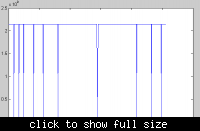
The image that I draw from Matlab after getting the output from Verilog is as under


Bests and Many thanks
Shan

---------- Post added at 12:25 ---------- Previous post was at 12:25 ----------

Dear,

Thank you for your response.

I am Using ISIM from Xilinx (ISE) as Modelsim is not working on my machine.
What is the input signal level?
Input Signal lelvel that I gave in Matalb is +/- 1 while I think we cannot give this in verilog.

Well my FFT is generated by Core generator
It has the following specs

real input : xn_re from external file
Imaginary input = 0 (given by me)
Input bits 20
output (unscaled) 27
rest if bits are common lie
dv= valid data
done, edone, rfd etc

It is taking 64 pieces of data in 1 time.( what I think problem lies with this thing, coz

The Matlab code for generation of since wave is as follows

The following is the code for Matlab for genreating and storing sine wave binary into a file
later called by verilog simulation model

Code:
clc; clear all;close all;

%Sine wave of freqeuncy 200
f=200;
T=1/f;
Tmax=5*T;
dt=1/10000;
t=-Tmax:dt:Tmax;
fid2=fopen('binary.txt','w');
x=100*sin(2*pi*f*t);
plot(t,x);

%converting floaing point into fixed point
%with 20 bit word lentgth and 18 bit fraction length
y=fi(x,1,20,18);

%Converting fixed point into respective binary notation
z=bin(y);

%Writing binary strings into file 'binary.txt'
for i=1:length(x)
    fprintf(fid2,'%s \r\n',z); 
end

fclose(fid2);


my verilog simulation model is as under: NOTE: I have not included the regs and variable declarations

Code:
	initial begin
	$readmemb("binary.txt",mem);  //taking Matlab data fro sine wave
	mcd = $fopen("from_verilg.txt"); //Opening a FILE to wirite
	end

	always #5 clk = ~clk; //running clock

	initial begin
		// Initialize Inputs
		ce = 1;	start = 1; clk = 0; xn_re = 0;	
		fwd_inv = 1; unload = 1; fwd_inv_we = 1; xn_im = 0;		
	end
    
		always@(posedge clk)
		begin
			if(rfd)
				begin
				if(i<=500)	begin xn_re <= mem[i]; i <= i+1'b1;	end		
				end
		end

	always@(negedge dv) if(i>= 500) $fclose(mcd);
	//counting 501 sample of sine wave input from Matlab

	always@(posedge clk)
	if(dv)	$fdisplay(mcd,"%b \n", xk_re);


The image that I draw from Matlab after getting the output from Verilog is as under


Bests and Many thanks
Shan
 
Last edited:

Status
Not open for further replies.

Part and Inventory Search

Welcome to EDABoard.com

Sponsor

Back
Top