oneitusatu
Junior Member level 3
Hi,
i am designing Low Resistance Measurement,my problem here is i need power supply that provide current source 5A and very low voltage almost zero(if it possible).
the resistance i would like to measure is in uOhm,,
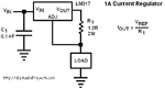
1)i was planning using ic regulator for current www.micrel.com/_PDF/mic69502.pdf ,, anyone have experienced using it?and wwhat is the problem?
2)i was planning using the dischargin of capacitor,so when caps is full then we have microseconds time at that discharging of the caps for measurement,ive tried a simple experiment with it and it could provide very low voltage and because of very low resistance in caps it could provide high current too?but my problem here is in measuring the voltage & ampere at that microseconds using microcontroller?have anyone tried the same thing?
3)what is the side effect if we have high drop out voltage?because my output would be at least 0,1volt?
4)is there any other/simpler way to get my specification current source?
Rgrds
i am designing Low Resistance Measurement,my problem here is i need power supply that provide current source 5A and very low voltage almost zero(if it possible).
the resistance i would like to measure is in uOhm,,
1)i was planning using ic regulator for current www.micrel.com/_PDF/mic69502.pdf ,, anyone have experienced using it?and wwhat is the problem?
2)i was planning using the dischargin of capacitor,so when caps is full then we have microseconds time at that discharging of the caps for measurement,ive tried a simple experiment with it and it could provide very low voltage and because of very low resistance in caps it could provide high current too?but my problem here is in measuring the voltage & ampere at that microseconds using microcontroller?have anyone tried the same thing?
3)what is the side effect if we have high drop out voltage?because my output would be at least 0,1volt?
4)is there any other/simpler way to get my specification current source?
Rgrds