Continue to Site

Welcome to EDAboard.com

Welcome to our site! EDAboard.com is an international Electronics Discussion Forum focused on EDA software, circuits, schematics, books, theory, papers, asic, pld, 8051, DSP, Network, RF, Analog Design, PCB, Service Manuals... and a whole lot more! To participate you need to register. Registration is free. Click here to register now.

How to create a rs232 standard in proteus

Status
Not open for further replies.

anhnha

Full Member level 6
Joined
Mar 8, 2012
Messages
322
Helped
4
Reputation
8
Reaction score
4
Trophy points
1,298
Activity points
3,684
Hi,
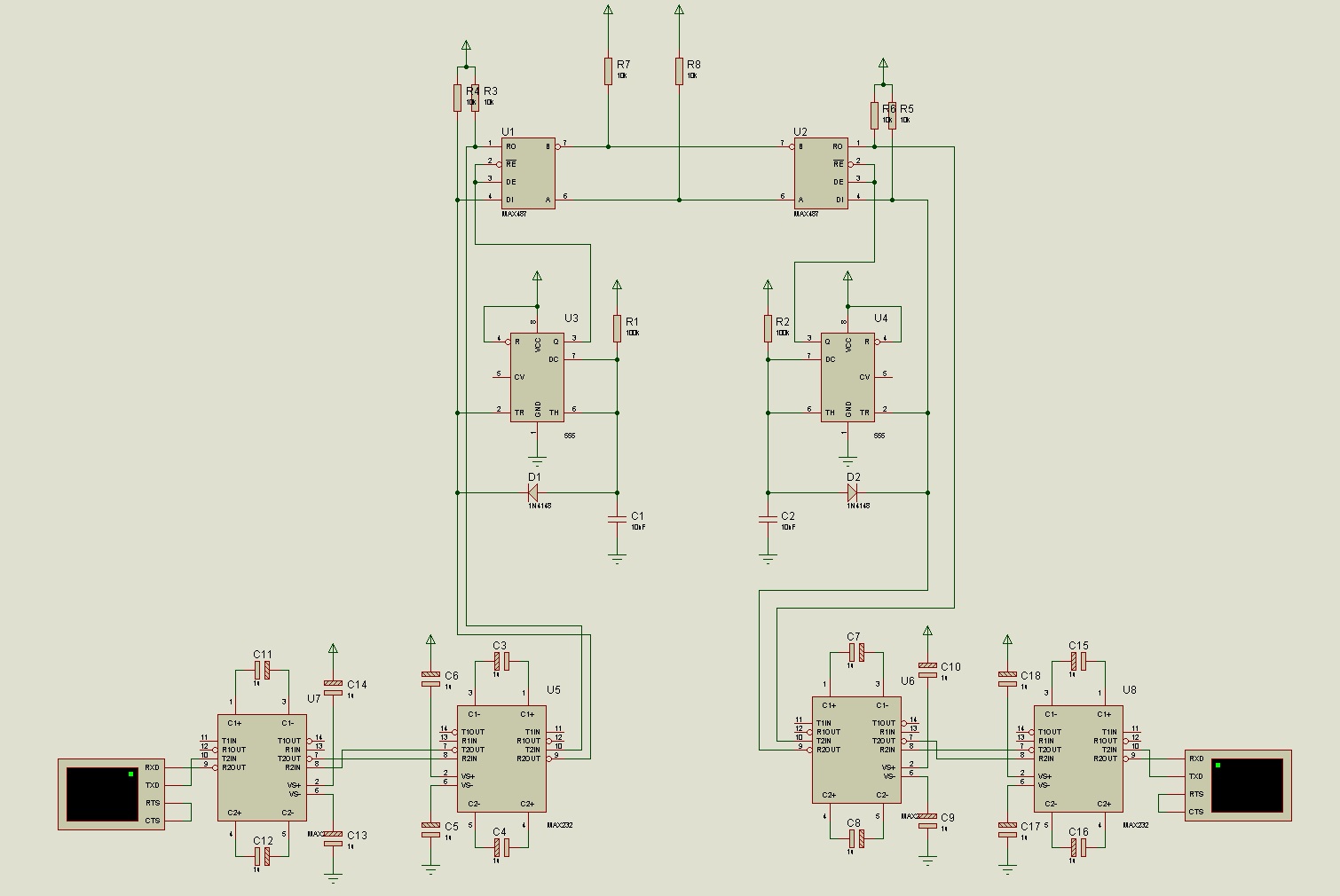
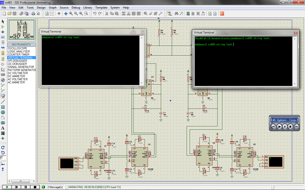
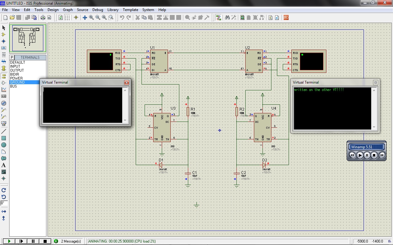
I wan't to simulate rs232 to rs485 in proteus but i can't create a rs232 voltage.I used compim but it is just TTL standard.How can I have RS232 standard to do it.Pleased help me,thanks.


Thanks for replying, can you help me check the schematic that i have draw in proteus.There are many things make me confusing:???:.In this schematic i can send and receive from/to both side.Would you give me the explain for these:
1.Why we need an invertor in this schematic?
2.Why I can send and receive data correctly while the input of Max232 is just TTL standard.How can i get the RS232 standard to MAX232 in proteus?
3.When i put a 555 timer in the other side to control receiving and sending but this is not work? I want to use 2 555 timer to control it.
Thanks you very much.

RS232-RS485 converter.png
 
Thanks for replying, can you help me check the schematic that i have draw in proteus.There are many things make me confusing:???:.In this schematic i can send and receive from/to both side.Would you give me the explain for these:
1.Why we need an invertor in this schematic?
2.Why I can send and receive data correctly while the input of Max232 is just TTL standard.How can i get the RS232 standard to MAX232 in proteus?
3.When i put a 555 timer in the other side to control receiving and sending but this is not work? I want to use 2 555 timer to control it.
Thanks you very much.

View attachment 71891
Sorry! I forgot this schematicrS232-RS485 CONVERTER2.png.Thanks in advance.
 

1. I think it's only for simulation... as the max232 is something like a voltage inverter
2. remember it´s only simulation... any way if you input TTL(0-5v) to a max232 it will work! and the output should be rs232 (-10v ~ +10v) but you have the inverter for that stuff..
3. i don´t see how your 555 is working... mmmm too lacy to draw your circuit and simulate it.... but the trigger should be connected to the TX output...


any way...

here is a datasheet AND CIRCUIT of a good rs232 to rs485 converter...
**broken link removed**

i buyed it and it worked charmly... any way it seems easy to build (note the max232 as a tsc232...
 
  • Like
Reactions: anhnha

    anhnha

    Points: 2
    Helpful Answer Positive Rating
Thanks very much.I am a newbie in electronic.Would you help me explain why this schematic not work.RS232 to RS485_converter.png.What is wrong in this,I can't find anything wrong but I is not work when i simulate in proteus.All i want to do is communicate between two computers and i have to convert from rs232 to rs485 and vice versa.I have removed Max232 because i think that in this case the output of vitural terminal has been TTL standard.
I really appreciate your help.


it worked! at least in simulation...

---------- Post added at 10:39 ---------- Previous post was at 10:34 ----------

please note all the components, and the values of R and C it's calculate for 1ms for a 9600bps communication... for other baudrates you need to recalculate... (cheat: i used the values from the pdf I posted previously :twisted:)
 
Thanks.It work well.But now i want to transfer TTL to rs232.I used two max232 to do that.one to trensfer TTL to rs232 and another to transfer RS232 to TTL,it occour a problem
is that when i type from one vitual terminal sometime it have error and sometime it work?the first letter is always wrong?Would you show me what happen?
This is my error and diagram:
convert1.pngerror2.png
 
i took my precious time to complete the circuit as you stated, with 2 max232... and, yes the first character, doesn't goes ok...


i just added some pullups, pulldowns (for simulation states)... and i think it´s ok, the first character glitch is something more of a simulation issue, so you wouldn't get rid of it from proteus isis....

but i'm very confident it will work on real life....
 
  • Like
Reactions: anhnha

    anhnha

    Points: 2
    Helpful Answer Positive Rating
Can you give me your circuit? I am doing it
 

here **broken link removed** check the schematic and adapt it yourself.
 

Status
Not open for further replies.

Similar threads

Part and Inventory Search

Welcome to EDABoard.com

Sponsor

Back
Top