jumpman
Newbie level 6
Good afternoon.
I am trying to use a TRIAC to turn on and off the mains connection to a load. This load is directly connected to the mains (without a transformer) because it is a Cockroft Walton Ioniser (with capacitors and diodes). I'd like to use the TRIAC with this configuration: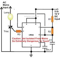 where the lamp is replaced by my load (ioniser).
Is it possible?
I am trying to use a TRIAC to turn on and off the mains connection to a load. This load is directly connected to the mains (without a transformer) because it is a Cockroft Walton Ioniser (with capacitors and diodes). I'd like to use the TRIAC with this configuration:
 where the lamp is replaced by my load (ioniser).
 Is it possible?