Continue to Site

Welcome to EDAboard.com

Welcome to our site! EDAboard.com is an international Electronics Discussion Forum focused on EDA software, circuits, schematics, books, theory, papers, asic, pld, 8051, DSP, Network, RF, Analog Design, PCB, Service Manuals... and a whole lot more! To participate you need to register. Registration is free. Click here to register now.

simple Kirchoff's current law problem

Status
Not open for further replies.

tarun0xe

Member level 2
Joined
Jul 25, 2011
Messages
47
Helped
8
Reputation
16
Reaction score
8
Trophy points
1,298
Location
India
Activity points
1,812
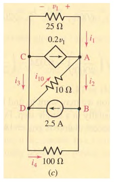
hello everyone...the file i have attached,contains a problem based on kirchoff's current law in which one needs to find all mentioned currents.i have proceeded by combining node A and B into one(since they are same potential points so they must be same node,i guess) and similarly combining node C and D too.in this way,i have applied KCL at node E say,which is the combination of nodes A and B and found currents i1,i4 and i10but what about current i2 and i3?????? they are not even present in my equivalent circuit....
in solution,after finding above currents i1,i4 and i10 KCL is again applied individually at nodes A and B in given figure to find i2 and i3....well thats simple but i thought that current i2 and i3 shouldn't exist as they are shown between same potential points A-B and C-D respectively and i think no current exists between same potential points......so where am i lagging the concepts..????please give your usefull suggestions....thanks in advance..:smile:...
7_1332074826.jpg
 

Hello,

The "wires" have zero resistance, so there can flow current with zero potential difference between (for example) A and B. You solved most currents by combining AB and CD (I would do the same). You know I4, and current from D to B (that is - 2.5A). So for node B: I2+I4+(-2.5) = 0.

Same reasoning is valid for I3: -I4+2.5A + I3 = 0.
 
Simplifying, there's only one R = 1/(1/100+1/25+1/10) = 20/3 Ω = 6.667Ω
Then v1/R = 2.5A - 0.2v1 ==> v1 = 2.5/(1/R+ .2) = 50/7 V = 7.143V

Knowing v1 the rest is trivial --> evaluate the current a R100...R10 , the current of dependant source,.....
 
I get v1 = 50 volts exactly, assuming that the VDCS is in the east direction when the v1 is positive.

Ratch
 
thanks everyone for your help.....so what i was lagging is that the wires(since assumed to have zero resistance) do carry currents even across zero potential difference...thank you so much WimRFP .....so do we have to take same assumption in all such problems and is there any explanation for such property???....and i think that since practically wire do have their own resistance too,that assumption shouldn't be valid for real circuits??? correct me if i am wrong.....thanks again... :smile:
 

In real world, there is wire resistance, but many times this can be ignored (especially in low current systems). One meter of copper wire with D=0.5mm has a resistance of about 0.1 Ohms. If you would insert a 0.1 Ohms resistor between nodes AB and AC, you will notice negigible difference. To save time, you may put the problem into a spice simulator. You can model your controlled current source with the Voltage Controlled Current Source in Pspice.

Other sign for virtually no influence is calculating the voltage drop across the inserted resistors based on your calculated currents. Generally spoken, if the resistance of the connecting wires in a series circuit is very low with respect to the total resistance in the series circuit, the wire resistance can be ignored in simple ballpark calculations. But be careful in practical circumstances...

In a 12V car electrical system, thick wires are used, especially for the starter. It can draw more then 200A from the car's battery. If you allow a voltage drop of <0.5V, the wire resistance should be less then 0.5/200 = 2.5 mOhms. A 1m long wire with D= 3mm has about 2.5 mOhms of resistance. The wire will dissipate 200A*0.5V = 100W during starting!

You can imagine that with this dissipation the wire's insulation will melt, therefore the actual cable from battery to starter is very thick.
 
....and i think that since practically wire do have their own resistance too,that assumption shouldn't be valid for real circuits???
Every material has resistance, but when is much smaller than the others in the circuit, or the voltage drop is less than the measuring error -> for practical purposes, can be considered zero resistance.

You can use a simulator and replace each piece of cable for ~0,001 ohm resistors (i.e.) and check that the result is "practically" the same.
 
Status
Not open for further replies.

Similar threads

Part and Inventory Search

Welcome to EDABoard.com

Sponsor

Back
Top