Continue to Site

Welcome to EDAboard.com

Welcome to our site! EDAboard.com is an international Electronics Discussion Forum focused on EDA software, circuits, schematics, books, theory, papers, asic, pld, 8051, DSP, Network, RF, Analog Design, PCB, Service Manuals... and a whole lot more! To participate you need to register. Registration is free. Click here to register now.

[SOLVED] Low pass filter combination

Status
Not open for further replies.

iVenky

Advanced Member level 2
Joined
Jul 11, 2011
Messages
584
Helped
37
Reputation
76
Reaction score
35
Trophy points
1,318
Location
College Station, Texas
Activity points
6,124
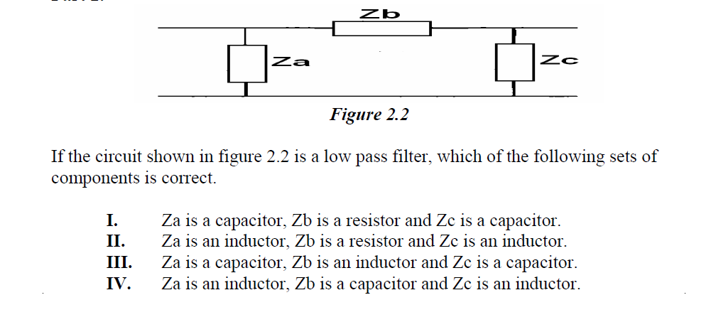
I have attached the image.

I am confused between the options (a) and (c).

What is the correct answer ( surely (b) and (c) are wrong) and how do you say that the other one is wrong?
 

even if this is answered by a third pary, whon and how you lean things, I wonder

however a simple LPF would have inductor inseries and capacitors in parallel
 

a sort of second level and preference is always to LC filters. and later on active filters

Ps:
a resistor need not have Z(impedance ) as it is a resistance.
Only capacitor and inductor, ( in pure components, as many times in pratice resistor wouls alo have a little of inductance ( CFR) and some capacitance ) would have impedance.
 
Last edited:
  • Like
Reactions: iVenky

    iVenky

    Points: 2
    Helpful Answer Positive Rating
To answer this question, consider that capacitors are open circuits at dc (low frequency) and short circuits at high frequency.
Also consider the fact that inductors are short circuits at dc (low frequency) and open circuits at high frequency.
With these two pieces of information, consider that the purpose of a LPF is to pass low frequencies from passing from input to
output and blocking high frequencies from passing from the input to the output.

It is clear that options II. and IV. are incorrect since there is shunt inductor which would block low frequencies -- not what we want from a LPF.
I. and III. are both LPFs. At dc, I. has a resistor between input and output while III. has a short (inductor) -- so low frequencies will pass through.
At high frequencies, both I. and III. have a capacitor shunt with the input and output, so the high frequencies will be blocked from reaching the output.
I. and III. are indeed lowpass filters.

--Vahe
 

To complete (and correct) the above answer it should be mentioned that a VOLTAGE driven filter was assumed.
The situation may look different for signals coming out of a current source.
 

The high or low-pass property doesn't depend on the source impedance, I think. But in case of zero source impedance (voltage driven circuit), the first shunt element Za will be meaningless and can be omitted. In so far, the problem seems to suggest a finite source impedance.
 
  • Like
Reactions: LvW

    LvW

    Points: 2
    Helpful Answer Positive Rating
The high or low-pass property doesn't depend on the source impedance, I think. But in case of zero source impedance (voltage driven circuit), the first shunt element Za will be meaningless and can be omitted. In so far, the problem seems to suggest a finite source impedance.

Yes, my comment ("situation looks different") was related to the general transfer characteristics (filter order) because the shunt element Za is meaningless for a pure voltage source.

---------- Post added at 11:34 ---------- Previous post was at 11:31 ----------

The main purpose of my comment was to point to the necessity for mentioning the source resistance for such a question.
 
  • Like
Reactions: FvM

    FvM

    Points: 2
    Helpful Answer Positive Rating
Status
Not open for further replies.

Similar threads

Part and Inventory Search

Welcome to EDABoard.com

Sponsor

Back
Top