Continue to Site

Welcome to EDAboard.com

Welcome to our site! EDAboard.com is an international Electronics Discussion Forum focused on EDA software, circuits, schematics, books, theory, papers, asic, pld, 8051, DSP, Network, RF, Analog Design, PCB, Service Manuals... and a whole lot more! To participate you need to register. Registration is free. Click here to register now.

[SOLVED] Thrifty voltage regulator, increase in current?

Status
Not open for further replies.

neazoi

Advanced Member level 6
Joined
Jan 5, 2008
Messages
4,119
Helped
13
Reputation
26
Reaction score
15
Trophy points
1,318
Location
Greece
Activity points
36,918
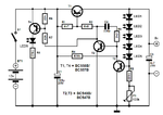
Hello I have found this regulator **broken link removed**
I have tested it and works like a charm. I have also managed to take other output voltages (8v) by adding some more leds and another potentiometer.
My question is, can I ingrease the output current which is now only about 20mA?

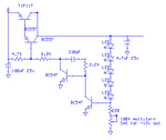
I have attached a proposition for this, coult wou tell me if this is ok?
Basically I am forming a pnp darlington by the use of 2 transistors. Will the small bc557 drive ok the big tip117? (I will consume about 1-1.5A max out of the PSU)
 

Attachments

  • vr.png
    vr.png
    8.5 KB · Views: 135

It should work but be careful, the LED characteristics vary as light falls on them so keep them in the dark if you want a contant voltage. The method of setting the voltage isn't very good because it uses the dynamic resistance of the LEDs which is not a defined parameter. It would be cheaper and more stable if you removed all the LEDs and fitted Zener diode instead. The output voltage will be the Zener voltage + the B-E drop (about 0.65V) in the bottom BC547.

Brian.
 
  • Like
Reactions: neazoi

    neazoi

    Points: 2
    Helpful Answer Positive Rating
It should work but be careful, the LED characteristics vary as light falls on them so keep them in the dark if you want a contant voltage. The method of setting the voltage isn't very good because it uses the dynamic resistance of the LEDs which is not a defined parameter. It would be cheaper and more stable if you removed all the LEDs and fitted Zener diode instead. The output voltage will be the Zener voltage + the B-E drop (about 0.65V) in the bottom BC547.

Brian.

Right, than you, I will try it!
 

Hello,
I have tried it and It did not work first time.
I have used a bd436 instead of a tip117 since I did not want to use a darlington.
I have used a zener like you mentioned. first a 9.1V one and then a 3.4V. how should the zener be connected by the way?
I have tried both connections for the zener.
I also measured the voltage at the base of the bc557, it is always close to the input voltage of the circuit (12v)
Still, I get something about 0.6V on the output (collector of the bd436) no matter how I set the potentiometer.
Could you give me any hints what could be wrong here?
 
Last edited:

It should be wired with the cathode (+) end toward the output point.
Looking closely at the schematic, are you sure the middle transistor is supposed to be a BC547 as there is no way to provide bias to it at the moment. I think either it should be PNP or the 2.2K resistor is in the wrong place.

Brian.
 
  • Like
Reactions: neazoi

    neazoi

    Points: 2
    Helpful Answer Positive Rating
It should be wired with the cathode (+) end toward the output point.
Looking closely at the schematic, are you sure the middle transistor is supposed to be a BC547 as there is no way to provide bias to it at the moment. I think either it should be PNP or the 2.2K resistor is in the wrong place.

Brian.

Yes, according to the original schematic it should be a bc547.
**broken link removed**
I have made the original schematic in the past and it worked ok.
Any clues what is happening?
 

Have you fitted R4 (in the original article), it provides bias for the BC547 but it is missing in your first schematic.

Brian.
 
  • Like
Reactions: neazoi

    neazoi

    Points: 2
    Helpful Answer Positive Rating
Have you fitted R4 (in the original article), it provides bias for the BC547 but it is missing in your first schematic.

Brian.

You are absolutely right!, I will try it.
Thanks a lot
 

You are absolutely right!, I will try it.
Thanks a lot


yes it worked now. but the stability is awful. I have tried removing the bd436 and make the circuit like the original. it still shows problems. I am pretty sure there is a mistake somewhere that I cannot spot of a component failure.
I think I am going to make the circuit from the beginning!
 
Last edited:

Hello Dear neazoi
As i understood , you need a variable power supply ?! ( with best stability) . ok why you don't try to design one of them ? for example , try LDO systems , what have best specifications .
Best Wishes
Goldsmith
 
  • Like
Reactions: neazoi

    neazoi

    Points: 2
    Helpful Answer Positive Rating
Try dropping R4 from 820K down to about 47K. I think the high value is starving the transistors of collector current and bias.

There are better schematics for small power supplies that use the same number of components. I have to leave for a while but I will post a similar but better schematic for you later today.

Brian.
 
  • Like
Reactions: neazoi

    neazoi

    Points: 2
    Helpful Answer Positive Rating

I think you are missing the point of the suggested circuit, have you read the article in the link of the first post?

One of the drawbacks of a three-pin voltage regulator is that the input voltage needs to be 2.5–3 V higher than the output voltage.
This makes these integrated regulators unsuitable for battery power supplies.
If, for instance, the output voltage is 5 V, a 9 V battery could be discharged to 7.5 V or thereabouts only.
On top of this, most of these regulators draw a current of about 2 mA.
Special low-drop versions sometimes offer a solution, but they are not ideal either.
The regulator described here is rather thriftier: it draws a current of only 300 µA and the difference between its input and output is only 100–200 mV In the circuit diagram, T1 is arranged as a series regulator, which means that the difference between input voltage and output voltage is limited to the transistor’s saturation potential.


LM317 has a minimum in-out difference of 3v

Alex
 
  • Like
Reactions: neazoi

    neazoi

    Points: 2
    Helpful Answer Positive Rating
Sorry. I concentrated on the current (1-1,5A) and the requirement that it should be adjustable.

We once built a circuit with a voltage regulator, a microprocessor and a couple of LEDs without studying the data sheet for the regulator. A tiny low power regulator. In the end we found out that by far the highest current consumption was in the regulator.
 
  • Like
Reactions: neazoi

    neazoi

    Points: 2
    Helpful Answer Positive Rating
I will power some crystal ovens with this PSU with a total of 600-800mA. Also this will power an ovenized varicap for setting the frequency of an oscillator. The voltage needs to be stable regardless of the input voltage. Small long term tolerations can be accepted. Simplicity and easiness of construction is an issue. This elektor regulator worked very good at first time for me but only for 5-8v tested.
 

So the small Vin-Vout difference is not a requirement?
 
  • Like
Reactions: neazoi

    neazoi

    Points: 2
    Helpful Answer Positive Rating
So the small Vin-Vout difference is not a requirement?

Think it that way. For an output voltage of 9v a 78xx regulator require at least 12v. A 12v battery is not allowed to be discharged lower than 12v for the circuit to operate. So a less I/O difference is a must.
 

It really starts to drive me crazy. I made it the way shown on the attachment. I included the low voltage option. The LED in the low voltage stays always on.
The voltage at the base of the t3 is more than 3v, whereas it should be something like 0.7v
Is there any case I have burned out a transistor?
 

Attachments

  • CONVERSION.png
    CONVERSION.png
    665.5 KB · Views: 88

The base-emitter junction of T3 is open circuit. The output voltage is set by T3's Vbe added to the sum of Vf of all the LEDS. If you think of T3's B-E junction as just being a diode you will see there is nothing limiting the current that flows through the LEDs and T3, they are all constant voltage junctions straight across the output. The way it works is T2 tries to make T1 fully conduct but T3 starves it of base current.

You have to be careful with this circuit, it will not tolerate any voltage higher than it produces at it's output. For example, if you connected a battery across the output to charge it, T3 would be killed by excessive base current. The way P1 works is also suspicious as all it does is divert some of T3's base current away. When you consider the effective resistance of the LEDs is just a few ohms, diverting current through 100K is never going to be very effective.

Brian.
 

Thank you.
I found the problem. It was a faulty T3. When I changed T3 with a new one everything worked as expected. I have finally used a zenner as you suggested. The output voltage with a 9.1v zener was 9.5v. The potentiometer won't be doing much setting on this high voltage so I omitted it, leaving only the 220R.

I will try replacing t1 with a more powerful transistor but not in darlington mode, to see what happens. I will let you know about the results for the common interest.

I won't connect a battery at the output, it is only as a reference voltage to drive a varicap and some crystal ovens. So there is no way voltage will come back from the input.
 
Last edited:

Status
Not open for further replies.

Similar threads

Part and Inventory Search

Welcome to EDABoard.com

Sponsor

Back
Top