Continue to Site
Follow along with the video below to see how to install our site as a web app on your home screen.
Note: This feature may not be available in some browsers.
Thanx every1 for Ur timely reply.
I'll check your approach. In mixer I'm using two RF chokes to give path to DC current. I just want to realize it using transmission lines.my design is in ADS. please suggests me some reading stuff that can tell the steps to make it possible using ADS.
I've a 1 more question.Actually I want to plot the conversion loss versus RF power graph in ADS. I'm not interested to use the build in equations of mixers templates in ADS design guide. I've used this equation ConvGain= dbm(V_out) + RFpower using measeq. But plots are not correct one inotherwords there are no results. please guide me how to write this equation.
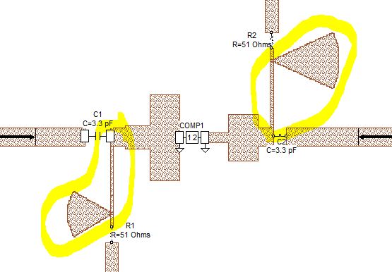
In additon to what enjunear has suggested: the next optional step is to replace the capacitor by a radial stub. Design the radial stub with radius = 1/4 wavelength, so that it represents a "short" at your frequency of interest. Together with the narrow 1/4 wavelength line, this is then transformed into an RF "open" at the circuit.