Continue to Site

Welcome to EDAboard.com

Welcome to our site! EDAboard.com is an international Electronics Discussion Forum focused on EDA software, circuits, schematics, books, theory, papers, asic, pld, 8051, DSP, Network, RF, Analog Design, PCB, Service Manuals... and a whole lot more! To participate you need to register. Registration is free. Click here to register now.

Can anyone explain me Bootstrapping with an example?

Status
Not open for further replies.

iVenky

Advanced Member level 2
Joined
Jul 11, 2011
Messages
584
Helped
37
Reputation
76
Reaction score
35
Trophy points
1,318
Location
College Station, Texas
Activity points
6,124
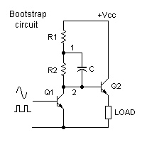
Hello. I want to know about what Bootstrapping exactly is. I would be really happy if you could provide some example with a circuit.

Thanks in advance.
 

Hello my friend
The technique to provide very high input impedance , called boot strap . see below figure , please:
Bootstrap.JPG
The out put is from collector. the voltage across the R4 is in the same phase and amplitude , thus , it considered , open circuit ( instead of AC signals. )
With this method , we can decrease , the effect of R1 and R2 at input resistance .
we can use the bootstrap method for the CC amp or CD amp to increase , the input resistance .
Best Wishes
Goldsmith
 
This circuit is one possible application of the bootstrapping principle.

15_1326819595.png


Let's examine how the circuit works, first without the capacitor. when the signal at the base of Q1 is going down, the collector current decreases and the voltage at the collector (point 2) rises up. This reduces the voltage difference between Vcc and point 2 and thus reduces the available base current to Q2. When point 2 approaches Vcc, there's very little base current available for Q2. But this is just when Q2 needs more base current to pull the load up.

Now let's insert C. When Q1 base is high and point 2 is low, C is charged to the voltage across R2. When Q1 base goes low and point 2 voltage rises, the charge across C cannot change quickly. To maintain the charge, point 1 is also pushed up. As point 2 rises, point 1 keeps rising too until it is even higher than Vcc. This makes base drive current continue to be available for Q2 when it's needed.

Of course, the charge in C is being drained by R1 and R2 so that it cannot maintain its charge indefinitely. Therefore, this technique can be used only if the RC time constant is long compared to a single period of the drive signal.

The same principles apply if Q2 is an N-channel MOSFET because a MOSFET needs a gate voltage much higher than the drain.

This action is called bootstrapping because raising the voltage at one end of the capacitor also raises the voltage at the other end just as pulling the end of a shoelace (bootstrap) transfers the tension though the holes to the lower end.
 
Last edited:
In general, it is a method of supplying power to a high-side NMOS driver of a switching half-bridge.
For a half bridge output to be driven high, the gate of the high-side NMOS must be driven above the supply of the half-bridge.
Some form of self-driven charge-pump configuration is used to generate this higher-than-supply voltage across a storage capacitor, otherwise known as the bootstrap capacitor, to power the high-side NMOS driver.

Dictionary definition of bootstrap : pull (oneself) up by (one's) bootstraps, to help oneself without the aid of others; use one's resources: I admire him for pulling himself up by his own bootstraps.
 
see FIG 2a of the following
**broken link removed**
 

checkmate's description of the term's origin (meaning the name, not the technique) seems to be more accurate than mine. And while a common application of bootstrapping is indeed for high-side driving of N-MOSFETs, the technique was actually used for other purposes long before power MOSFETs became available.

One common application is in audio amplifiers. It was particularly popular before PNP-NPN complementary BJT pairs were easily available and is still used in many simple circuits. Here's a very simple example of a circuit I designed and built many times in the past. All transistors were germanium, not silicon. The speaker and output capacitor are part of the bootstrap circuit.

41_1326877886.png
 
Last edited:
  • Like
Reactions: iVenky

    iVenky

    Points: 2
    Helpful Answer Positive Rating
I tend to associate with techniques for increasing input impedance for example. It can be used to reduce input capacitance in transimpedance amplifiers or reducing the effect of photodiode capacitance by 'bootstrapping' the opposite side of the photodiode to the one used for the input.

Keith
 

checkmate's description of the term's origin (meaning the name, not the technique) seems to be more accurate than mine. And while a common application of bootstrapping is indeed for high-side driving of N-MOSFETs, the technique was actually used for other purposes long before power MOSFETs became available.

One common application is in audio amplifiers. It was particularly popular before PNP-NPN complementary BJT pairs were easily available and is still used in many simple circuits. Here's a very simple example of a circuit I designed and built many times in the past. All transistors were germanium, not silicon. The speaker and output capacitor are part of the bootstrap circuit.

41_1326877886.png

How does it increase the input impedence?

Thanks for explaining me about bootstrap.
 

How does it increase the input impedance?
It doesn't. The purpose of boostrap in this case is to keep the voltage across the driver stage pull-up resistor constant, and thus allow sufficient driver current even near the positive supply voltage.

The bootstrap application addressed by Keith is of different nature.

The circuit in post #3 doesn't utilize bootstrap in my opinion, it's just a partly bypassed load resistor.

Bootstrap is a generic term. Although there are some features common to different kinds of bootstrap circuits, they don't bring you far in explaining the specific circuit operation.

Okay but I studied that it's indeed possible to increase the input impedence using bootstrap configuration. What is that configuration? How does it work?

Thanks in advance.
 

Okay but I studied that it's indeed possible to increase the input impedence using bootstrap configuration. What is that configuration? How does it work?
The circuit posted by Goldsmith in post #2 shows the basic configuration. Resistor and capacitor values should be adjusted according to the application requirements however.

Horowitz is showing exactly the two bootstrap variants from post #2 and post #6, of course with more explanation.
 

Status
Not open for further replies.

Part and Inventory Search

Welcome to EDABoard.com

Sponsor

Back
Top