Continue to Site

Welcome to EDAboard.com

Welcome to our site! EDAboard.com is an international Electronics Discussion Forum focused on EDA software, circuits, schematics, books, theory, papers, asic, pld, 8051, DSP, Network, RF, Analog Design, PCB, Service Manuals... and a whole lot more! To participate you need to register. Registration is free. Click here to register now.

[SOLVED] want to build ir receiver of 38khz

Status
Not open for further replies.
a simple circuit for receiver

**broken link removed**

---------- Post added at 10:23 ---------- Previous post was at 10:22 ----------

but this is transmitter, i am asking about receiver

both are in the same circuit

a simple receiver

**broken link removed**
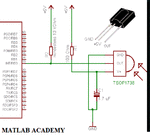
 

I make tpetar's circuit its work nice! I using it few month, and no problems.
 

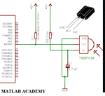
Here is the Circuit to detect IR with the Help of Micro-Controller...PIC16F877A

tsop1738.GIF
 
tsop 1738 is actually made for receiving the ir beam of 38khz but i am not having the schematic to do so, and the circuit given in its datasheet asks to connect directly to microcontroller, but my use is after detection their should be any led which shows the beam is received and after led the signal is sent to the microcontroller, if any one have any schematic with tsop pls share it here

---------- Post added at 23:51 ---------- Previous post was at 23:46 ----------

ok its almost what i am looking for, i have one doubt can you please explain its working? like even if i dont connect the microcontoller then can i get if the beam is received or not?
 

tsop 1738 is actually made for receiving the ir beam of 38khz but i am not having the schematic to do so, and the circuit given in its datasheet asks to connect directly to microcontroller, but my use is after detection their should be any led which shows the beam is received and after led the signal is sent to the microcontroller, if any one have any schematic with tsop pls share it here

This means that u can't even glow an led when your IR Beam is Received...
Okay
You dedicate a Controller pin for that purpose....
Means whenever you detect a IR beam just Put that pin high....

This is Programmatic way to do so..
or u can use an led and place it in on the Out pin of the TSOP.. i had not tested all this but it should work..
 
ok so if i connect the circuit that you have given to me then when it receive the ir beam it makes the pin33 high? means set it to 0?
 

1->GND
2->VS
3->Vout

This is the Pin Configuration of TSOP1738
and its output is active low:-
(Refer datasheet may be i am wrong..)

When IR is not there u will get 5V at its Output
and when IR is u will get 0V-5V in the form of pulses. means high low pulses.

Okay
ok so if i connect the circuit that you have given to me then when it receive the ir beam it makes the pin33 high? means set it to 0?

Not exactly... i mean to say u cann't notice it..
because when u connect multimeter pin to 3 pin and GND of TSOP u will get around 4V..
This is because
When u get IR which is at the rate of 38Khz
okay
the TSOP is also giving its a the same rate or little bit slower...
means low high low high...

Do u understand what i want to say..
If not then ask me
 
ya ya you mean tsop is also fluctuating its output at the rate of 38khz? or i say the output of tsop will be fluctuating like a square wave?
 

Yes u can say this but not exactly...

Here is the Waveform...
Capture-2.png

Hope this Helps u
 
Radio Shack carries an IR receiver module for 38kHz. Link:

38kHz Infrared (IR) Receiver Module - RadioShack.com

It has 3 terminals. Two are for power. The last one is an output which changes state when the photodetector receives a 38 kHz IR light beam.

I purchased one and it works well. It should not have a bright light shining on it, since it will reduce performance.
 

Yes u can say this but not exactly...
Here is the Waveform...
View attachment 67323
Hope this Helps u
as it is fluctuating output, the coding for uC for on/off a port like switch will be difficult, isnt it ?,
whenever the output fluctuates, then the uC output port also fluctuates, isnt it ?
means, attaining a stable state is difficult, isnt it ?
 
as it is fluctuating output, the coding for uC for on/off a port like switch will be difficult, isnt it ?,
whenever the output fluctuates, then the uC output port also fluctuates, isnt it ?
means, attaining a stable state is difficult, isnt it ?

Yes u are right its difficult...
But at least we can detect...

If have to detect a IR i would simple place a LED and a Buzzer to Detect the IR..
and If have to detect it using a Controller then i will take help of the Interrupt..
In this following snap ,TSOP is connected to the INTERRUPT pin of the Controller..

tsop1738.GIF

I haven't detect IR with the help of a Controller..
But i think we can detect it..
 
Sorry i am not having much idea regarding this...
As i haven't use uC with IR receiver and Transmitter...

Sorry Dear
 
sorry for late reply i tried that circuit given by arunsharma0731 . but the problem is the led glows all the time and when the ir beam is present it blinks but doesnt switches to off state, so i can observe that it is receiving the ir but how microcontroller would read this as it is fluctuating. as said in above post by varunme . is there any way to do this pls share it
 

but the problem is the led glows all the time and when the ir beam is present it blinks but doesnt switches to off state
There's no LED shown in the circuit by arunsharma0731, so you should clarify in a first place how you connected it.

Secondly, you have the problem that a RC IR receiver is very sensitive but isn't prepared for continuous 38 kHz modulation, so you would need to apply a second (pulse packet) modulation to use it e.g. for a light barrier.

The problem and possible solutions have been discussion in various same topic threads at Edaboard.
 

@Hiten09

The TSOP1738 cannot easily drive an LED directly. Its maximum current output is 5 mA according to the datasheet. Here is a link to using a TSOP1738 to drive a relay. It uses a small, common transistor to amplify the current. You could replace the relay with an LED and resistor.

Circuit diagram for relay activation using TSOP 1738

While that circuit may not meet all of your needs, it will give you a start to see whether your transmitter is working the way you want it to work.

John
 

@FvM
actually when i was discussing this with arunsharma0731 i asked him that can i connect the led to that output pin which is connected to the microcontroller.. so thats why i said its not working.
Secondly, you have the problem that a RC IR receiver is very sensitive but isn't prepared for continuous 38 kHz modulation, so you would need to apply a second (pulse packet) modulation to use it e.g. for a light barrier.
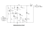
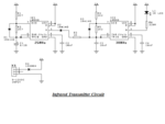
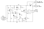
i didnt got what are you saying, ok i am attaching the circuit of transmitter and receiver both, this transmitter is working but in receiver part i had made some changes can you solve what problem it is havingir receiver circuit.pngir transmitter circuit.pngoriginal.png
 

@jpanhalt
it is having same problem, just have a look at the above post i attached two circuit one is named ir receiver circuit and another is named original. actually i wants to drive a led and after that i wants to connect it to microcontroller so that i could use this for further work as a interrupt
 

Status
Not open for further replies.

Similar threads

Part and Inventory Search

Welcome to EDABoard.com

Sponsor

Back
Top