Continue to Site

Welcome to EDAboard.com

Welcome to our site! EDAboard.com is an international Electronics Discussion Forum focused on EDA software, circuits, schematics, books, theory, papers, asic, pld, 8051, DSP, Network, RF, Analog Design, PCB, Service Manuals... and a whole lot more! To participate you need to register. Registration is free. Click here to register now.

[SOLVED] How can we change the state of 3 adjescent

Status
Not open for further replies.
varunme said:
On compiling, gives

volatile unsigned char port_C = PORTC; //save PORTC
err: constant expression expected.

I am using mikroC

I am not using microC, my compiler compiles it just fine.

Try this:

Code:
volatile unsigned char port_C;
port_C = PORTC; //save PORTC

Please check this and reply for the results.
 
  • Like
Reactions: varunme

    varunme

    Points: 2
    Helpful Answer Positive Rating
compiling , but in simulation , not works

Code:
   unsigned char i;


volatile unsigned char port_C;
volatile unsigned char port_D = 0;

void main() {

  trisc=0xff;
  trisd=0x00;

     port_C = PORTC; //save PORTC
for(i = 0; i < 8; i++)
{
  if (port_C&(1<<i))
  {
    port_D |= (1<<i);
    if (i)
      port_D |= (1<<(i-1));
  }
}

PORTD = port_D;  //update PORTD

}
 

varunme said:
compiling , but in simulation , not works
Can you please be more specific? In my simulation it works all right.
 

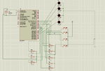
I meant in proteus, when connected with switches as below , when i press switches the lights wont glow ,

Alex proteus.png
 
  • Like
Reactions: alexxx

    alexxx

    Points: 2
    Helpful Answer Positive Rating
But with other example it works, i will check with resistor,
Not working with resistor added too
 

varunme said:
Not working with resistor added too
Then you could add a main loop and see what happens.

Code:
   unsigned char i;


volatile unsigned char port_C;
volatile unsigned char port_D = 0;

void main() 
{

  trisc=0xff;
  trisd=0x00;
  while (1)
  {
    port_C = PORTC; //save PORTC
    for(i = 0; i < 8; i++)
    {
      if (port_C&(1<<i))
      {
        port_D |= (1<<i);
        if (i)
          port_D |= (1<<(i-1));
      }
    }

    PORTD = port_D;  //update PORTD
  }
}
 
  • Like
Reactions: varunme

    varunme

    Points: 2
    Helpful Answer Positive Rating
yes, it works
As soon as I push a button in c , the corresponding one in D is lighting up

Now we have to apply the PWM

and a method for making the off ones 50%
 

But there is a problem , I have to light up one light in advance
 

Hai varun.. i thought the problem of glowing the adjacent lights, is solved. I didn't notice you are still in that. Did you faced any problem with the previous solution? because i didnt see you have mentioned the problem with that solution in any of your post.

By the way i think, i have a solution to reduce the intensity of LED.


I don't know much about AC circuits. So as per the image, there are 2 resisters one is with switch other is always connected. The resister values are designed to deliver half the current of LED's spec. When the switch can be activated based on the sensor input, the other resister will make your resistance of the network by half, which will result you 100% (saturation voltage) illumination to the LED.

I think you can replace the switch using opto-triac IC.
 

We cant use the Resistor for reducing the intensity, Have to use PWM , because out aim is to save energy, Thanks for your circuit, may be useful later
I am using DC

PDL for my task is like this , please review the same , How can we attain this programatically ?

View attachment 672

The picture posted above have some problems,

The sensor got deactivated as soon as the vehicle passes away, so it cant be seen as 1 in the second step, any workaround for this ?
 
Last edited:

hai varun...

i am not sure how much clear about this idea. But i think you can develop this for further level. The idea is " 1. Feed the sensor output to a flip flop, which will hold the status when some vehicle passes. 2.reduce the adjacent light intensity gradually even if the sensor output is down."

Here you may find another problem like, when first interrupt comes, the flip flop will hold high and when u get another interrupt u get low. So i recommend you not to check high or low but you can check the changes of previous and present state of the port pins. So when one vehicle crosses you will find the new status is high and another vechicle crosses you can confirm the state again changed so you have to lit the adjacent lights.

This may solve the problem of holding the state and also gives you some logical problems but i hope those can be resolved.

Thanks...
 
  • Like
Reactions: varunme

    varunme

    Points: 2
    Helpful Answer Positive Rating
hai varun...

i am not sure how much clear about this idea. But i think you can develop this for further level. The idea is " 1. Feed the sensor output to a flip flop, which will hold the status when some vehicle passes. 2.reduce the adjacent light intensity gradually even if the sensor output is down."

Here you may find another problem like, when first interrupt comes, the flip flop will hold high and when u get another interrupt u get low. So i recommend you not to check high or low but you can check the changes of previous and present state of the port pins. So when one vehicle crosses you will find the new status is high and another vechicle crosses you can confirm the state again changed so you have to lit the adjacent lights.

This may solve the problem of holding the state and also gives you some logical problems but i hope those can be resolved.

Thanks...
can u give further example ?
 

varunme said:
Now we have to apply the PWM

and a method for making the off ones 50%

One important question is if your controller has as much PWM pins as you desire. If it hasn't then you must in any case implement this by software PWM. If it has, then you must give a clue of how are you going to implement this. There are 3 options that I can think of right now.

One is to use hardware PWM (if so many PWM pins are available).
Another option is to use software PWM, that is with the use of a timer interrupt and a counter inside interrupt.
A third option is to only set and clear pins as you succesfully do until now, and use external circuitry to produce the PWM. I wouldn't recommend this, it is expensive.

Please make your thoughts clear on this, so that we have a better picture.
 

The third option to produce pwm by setting and clearing pin needs external circuitry ?
 

varunme said:
The third option to produce pwm by setting and clearing pin needs external circuitry ?
Yes it does. In my opinion it is not a good idea to do so.
I don't know how many pwm pins you have available. Could you confirm this?
You must be sure what kind of pwm you need. Software or hardware?
If you lack PWM pins, then software implementation is the only way.
 

Yes it does. In my opinion it is not a good idea to do so.
I don't know how many pwm pins you have available. Could you confirm this?
You must be sure what kind of pwm you need. Software or hardware?
If you lack PWM pins, then software implementation is the only way.
The design we are using, suits software one, and for prototyping , we use 16F877a , have only two PWMs
 

The design we are using, suits software one, and for prototyping , we use 16F877a , have only two PWMs
Then the soft pwm is the option. In what frequency? Because soft pwm cannot go to really high frequencies. It is not "fire and forget" like hard pwm. You need to run code inside timer interrupt. If the frequency is very high, then the interrupt will be coming all the time and the rest of the code will run slow. But again this may not be a problem in some applications. So what frequency do you need?
 
Last edited:

Then the soft pwm is the option. In what frequency? Because soft pwm cannot go to really high frequencies. It is not "fire and forget" like hard pwm. You need to run code inside timer interrupt. If the frequency is very high, then the interrupt will be coming all the time and the rest of the code will run slow. But again this may not be a problem in some applications. So what frequency do you need?
Its to control LEDs so, is the frequency really accounts ?
 

Status
Not open for further replies.

Part and Inventory Search

Welcome to EDABoard.com

Sponsor

Back
Top