Welcome to our site! EDAboard.com is an international Electronics Discussion Forum focused on EDA software, circuits, schematics, books, theory, papers, asic, pld, 8051, DSP, Network, RF, Analog Design, PCB, Service Manuals... and a whole lot more! To participate you need to register. Registration is free. Click here to register now.
Meander Line antennas are normally lambda/2 or lambda/4 antennas. The idea is to fold the antenna element back and forth to make the overall antenna shorter.lets say your antenna is a monopole on a groundplane. its just your monopole dimensions folded back and forth,you will have to tune the foldings in horizontal and vertical direction to get proper VSWR response.
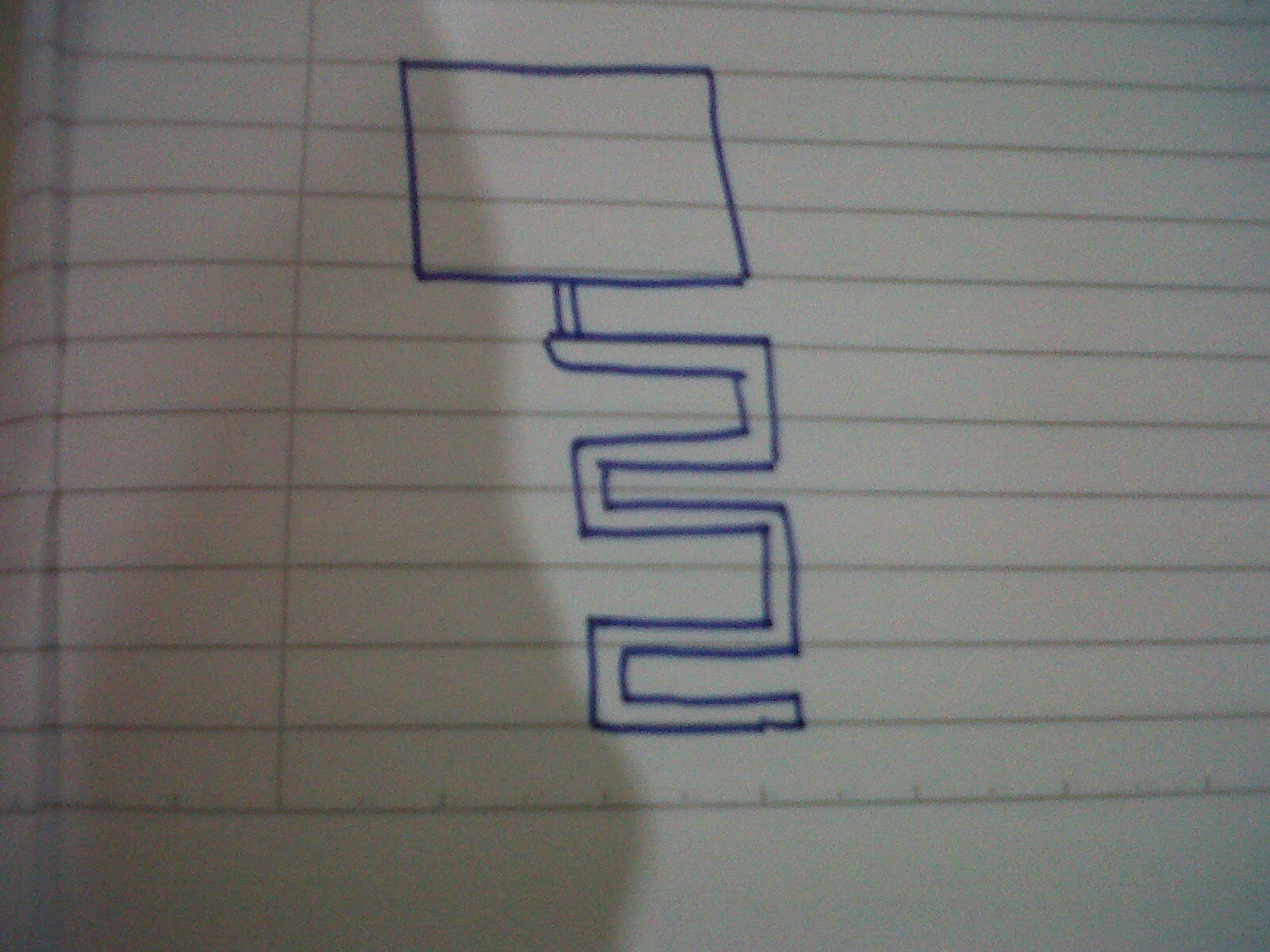
Patch and meander line! Hmm why two different radiating elements. do you have a paper that you are taking inspiration from,mya be it will give a better idea of what you are wanting to do
actually i got this pattern of antenna from my lecturer. he said this one can improve the gain and he ask me to get the dimension of the design. So, i thought there must be any formula to calculate the dimension like the width or length. and how much should i fold the antenna element back and forth.
There are some empirical formulas for meander-line dipole, though not much. As I can remember, in the recent issue of Antennas and propagation magazine, there is a paper purposing a formula to assist the meander-line dipole design. The formula is developed based on a database consisted of many fullwave simulation results. However, I think the formula may not applied in your case. First, the geometry is a bit different. Second, the meander-line u plotted looks like the feed-line of the patch. Are u sure strong radiation is desired from the meander-line?
hi all
you can calculate the model which your lecturer was give you
u can read some hand book of microstrip or read this"Lumped Elements for RF
and Microwave Circuits"
and about your lecturer idea i should say u i think this method didn't help u
to achieve higher gain
tq for the replies. even me also not sure whether the design can give higher gain or not. but i will try to design it first and go through with the result. my lect ask me to do this kind of design. maybe he wants me to see or learn something.
This site uses cookies to help personalise content, tailor your experience and to keep you logged in if you register.
By continuing to use this site, you are consenting to our use of cookies.