mrarslanahmed
Full Member level 2
- Joined
- Nov 15, 2011
- Messages
- 143
- Helped
- 6
- Reputation
- 12
- Reaction score
- 6
- Trophy points
- 1,298
- Location
- gujranwala pakistan
- Activity points
- 2,205
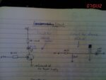
i have used two resistance in series (combined 200Ω)at the BAse while a single 100Ω resistance at the collector . emitter is directly grounded
")