papunblg
Advanced Member level 3
- Joined
- Oct 22, 2010
- Messages
- 716
- Helped
- 172
- Reputation
- 344
- Reaction score
- 165
- Trophy points
- 1,343
- Location
- Kolkata India
- Activity points
- 6,421
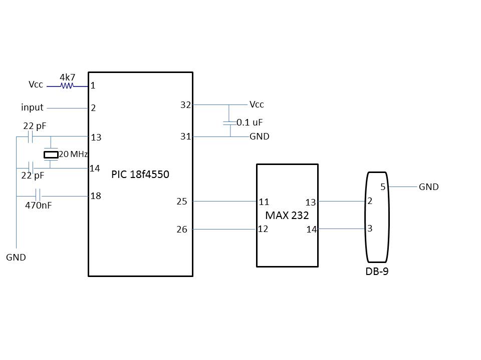
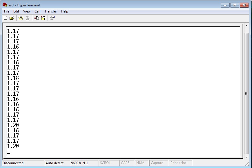
For a stable 5 Volt supply, voltage =1023.(Full scale). Use Send_Value () to send the content of voltage variable to Hyperterminal and check what is getting printed. If it is different (it should be 1023) Check the voltage of Vref+ pin(pin 5). How the Vref+ is connected. Publish the Schematic.


")