tonyctsiu
Member level 1
Dear All,
I am figuring out how the CC1110 balun is calculated based on the suggestion of the IEEE paper to verify the values of the lumped element suggested in CC1110 433 Reference design:
Lumped and Distributed Lattice-type LC-Baluns in microwave symposium digest 2002 Volume1
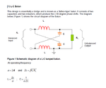
Please find the untitled.png for calculation and the cc1110ckt.png for reference design by TI's CC1110 at 433 MHz
Here is the calculation based on the suggested equation by IEEE paper. However It seems that the IEEE paper does not explain how to deal with complex R1 so I just put 116 ohm in the calculation instead of the 116-j*41 suggested by TI.
R1 116
RL 50
Zc 76.15773106
f 4.33E+08
omega 2.72E+09
L 2.80E-08=28nH
C 4.83E-12=4.8pF
Does any one know how to calculate the values of lattice balun if the R1 is a complex value?
Also it seems that TI has chosen C = 3.9 instead of 4.8pF. In what basis do they make such calculations?
Regards,
Tony
I am figuring out how the CC1110 balun is calculated based on the suggestion of the IEEE paper to verify the values of the lumped element suggested in CC1110 433 Reference design:
Lumped and Distributed Lattice-type LC-Baluns in microwave symposium digest 2002 Volume1
Please find the untitled.png for calculation and the cc1110ckt.png for reference design by TI's CC1110 at 433 MHz
Here is the calculation based on the suggested equation by IEEE paper. However It seems that the IEEE paper does not explain how to deal with complex R1 so I just put 116 ohm in the calculation instead of the 116-j*41 suggested by TI.
R1 116
RL 50
Zc 76.15773106
f 4.33E+08
omega 2.72E+09
L 2.80E-08=28nH
C 4.83E-12=4.8pF
Does any one know how to calculate the values of lattice balun if the R1 is a complex value?
Also it seems that TI has chosen C = 3.9 instead of 4.8pF. In what basis do they make such calculations?
Regards,
Tony