Continue to Site

Welcome to EDAboard.com

Welcome to our site! EDAboard.com is an international Electronics Discussion Forum focused on EDA software, circuits, schematics, books, theory, papers, asic, pld, 8051, DSP, Network, RF, Analog Design, PCB, Service Manuals... and a whole lot more! To participate you need to register. Registration is free. Click here to register now.

Dynamic port bit in PIC 16F877a using loop

Status
Not open for further replies.
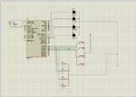
Publish the schematic. Its importent! A pin may get high or low upon closing depending on how it is connected.

img_1224968365_15182_1248019950_mod_349_266.jpg


Figure shows two common ways to interface switches to a microcontroller input. Input P0 uses R1 as a pull up. If SW1 is open, P0 will be high, and read as a logical 1. When SW1 is closed, pin P0 is shorted to ground, or 0V, and P0 will read as a logical 0.

P1 has R2 as a pull down resistor. When SW2 is open, P1 is pulled low, and read as a logical 0. Closing SW2 causes current to flow through R2, raising the voltage at P1 to the Vcc level. At that point P1 will read as a logical 1.

Note that some microcontrollers have internal pull up resistors that can be enabled under program controller. You don’t need to wire up R1 if you use an internal pull up resistor. If you use an external pull up resistor, tie the high end to the same voltage used to run the microcontroller. Using a higher voltage will damage the microcontroller, and a lower voltage may result the circuit not working.

More details and Selecting Resistor Values---> see Interfacing switches to microcontrollers
 
Last edited:
  • Like
Reactions: varunme

    varunme

    Points: 2
    Helpful Answer Positive Rating
This is my proteus file
 

Attachments

  • Loop2.zip
    30 KB · Views: 58

screenshot of the circuit

my switch.png
 

Looking at your previous code, you should use:
TRISD = 0x0F;

I don't know how detailed is Proteus' simulation, but you should use pull down resistors on the inputs and limiting resistor on LEDs.

You must pull high the MCLR pin for PIC to work.
 

it may better work on a real hardware than in simulation isnt it ?
 

it may better work on a real hardware than in simulation isnt it?

Not unless you want to burn up your LEDs, as Bjuric commented you need current limiting resistors and pull up or pull down resistors on your switches. Also as commented early, TRISD = 1 only sets the first pin of the PORTD, RD0, as input for the entire PORTD to be correctly configured as inputs use TRISD = 0xFF. Although TRISD is set to 0xFF and PSPMODE is disabled on reset , so I doubt that is your problem. If I have time I will modify your simulation in Proteus and see if I can get your code to perform as expected.

BigDog
 
  • Like
Reactions: varunme

    varunme

    Points: 2
    Helpful Answer Positive Rating
extremely sorry, BigDogGuru. My fault. It should be TRISD=0xFF. Corrected above now.
 

extremely sorry, BigDogGuru. My fault. It should be TRISD=0xFF. Corrected above now.
Not a fault actually, its a way of tightening our toolsuite.
 
The code didnt worked on an actual hardware too
 

The code didnt worked on an actual hardware too

Sir Varunme,
Happy New Year.

The following code (published earlier) has been tested on actual hardware and giving desired result:-
Remember that the code is tested on an old board where port A and Port B were pulled up using 1K resistors , so the result is some different according to the connection. Here If I close a switch on PORTA, an LED goes off at PORTB.

I also tested some of the other codes published above, they are also giving correct results. It appears that the problem you are facing due to Hardware connection. Modify your Hardware as BigDogGuru suggested already Also read the datasheet for correct settings of multi function pins.

#include <htc.h> //Hitech C compiler and 16F876a micro
#define _XTAL_FREQ 20000000
__CONFIG(FOSC_HS & WDTE_OFF & LVP_OFF & CPD_OFF & WRT_OFF & DEBUG_OFF & CP_OFF);


main(void)
{
unsigned char mybyte;
ADCON1=6;
TRISA=0xFF;
TRISB=0;

while(1){
mybyte=PORTA;
__delay_ms(50);
PORTB=mybyte;
}
}

Remember use of PULL UP or PULL Down for switches change the logic .
switch.png
 
Last edited:

I dont use proteous simulator so could not open files present in Loop.zip. A schematic would be more useful.
 
Last edited:

This is the schematic showing standard connection(But remember that I have tested above codes using 16F876a:-
sch.png
 
Last edited:

modified schematic in proteus
 

Attachments

  • loop.png
    loop.png
    43.9 KB · Views: 77

Status
Not open for further replies.

Similar threads

Part and Inventory Search

Welcome to EDABoard.com

Sponsor

Back
Top