muffassir
Member level 3
- Joined
- Sep 15, 2011
- Messages
- 67
- Helped
- 10
- Reputation
- 20
- Reaction score
- 10
- Trophy points
- 1,288
- Location
- Planet Earth
- Activity points
- 1,802
Hi all;
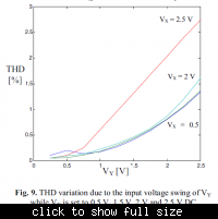
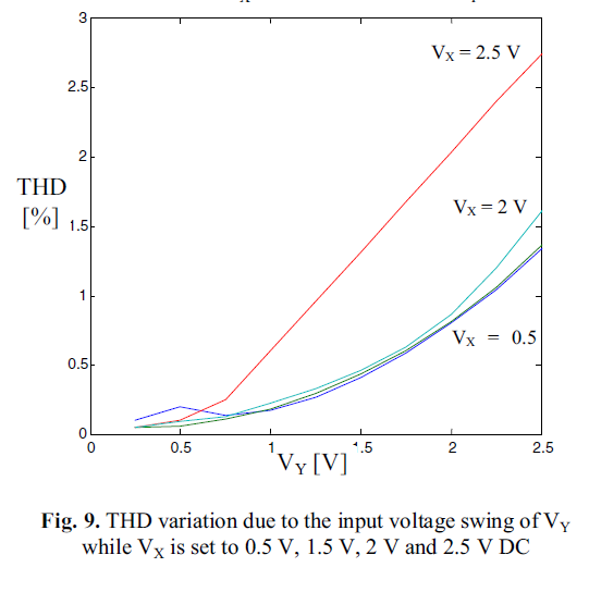
I want to calculate the total harmonic distortion (%) of my analog circuit.. I have two inputs as Vx and Vy ..Wherein i want to plot the THD variation due to input voltage swing between 0 and 1.8V(instead of 2.5V as shown in the pic called THD) while Vx set to different DC values.
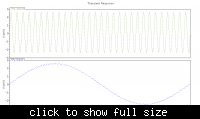
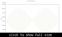
I want the waveform like this(only tech is different that is here it is 350nm and i am using 180nm )
My input are two i.e. Vx and Vy,
Vx
Dc Voltage=0V
AC Mag=1.8
Amplitude =5m
Freq=10KHz.
Vy
Dc Voltage=0V
AC Mag=1.8
Amplitude =5m
Freq=300KHz.
The circuit is a multiplier circuit. and output is Current.
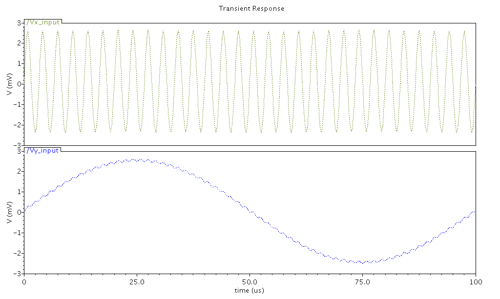
The input trans analysis is as below and the output is also below.
Please specify what fields i have to fill(the value) step by step ..and how can i draw the THD% Vs Vy as shown in first fig.
How can i do that in cadence . I am using Cadence 6.1.4.500 and ADE L . and gpdk180.
Thanks in advance..")
I want to calculate the total harmonic distortion (%) of my analog circuit.. I have two inputs as Vx and Vy ..Wherein i want to plot the THD variation due to input voltage swing between 0 and 1.8V(instead of 2.5V as shown in the pic called THD) while Vx set to different DC values.
I want the waveform like this(only tech is different that is here it is 350nm and i am using 180nm )
My input are two i.e. Vx and Vy,
Vx
Dc Voltage=0V
AC Mag=1.8
Amplitude =5m
Freq=10KHz.
Vy
Dc Voltage=0V
AC Mag=1.8
Amplitude =5m
Freq=300KHz.
The circuit is a multiplier circuit. and output is Current.
The input trans analysis is as below and the output is also below.

Please specify what fields i have to fill(the value) step by step ..and how can i draw the THD% Vs Vy as shown in first fig.
How can i do that in cadence . I am using Cadence 6.1.4.500 and ADE L . and gpdk180.
Thanks in advance..