Liamlambchop
Member level 2
Hey guys,
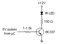
I have an arduino which is blinking an infrared emitting diode (IED) at a frequency of 38kHz. The arduino outputs 40mA per digital output pin, and I need about 100mA. I am unable to program the arduino to simultaneously turn on and off 3 pins at 38kHz, so I want to use a transistor to give me the extra current I require.
I have never designed a circuit with a transistor in it before (yes, I'm in the infancy of my electronics education), so I need some help with how to integrate it.
I have two options for extra power sources:
1. Is from the source which powers the arduino itself. This is a 12V, solar panel charged, battery.
2. Is from 2 other pins on the arduino (each pin can output 40mA at 5V).
So, how can I get my IED drawing 100mA using a transistor?
Thanks!!!!
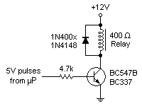
") )) I'm going to go with the circuit you suggested pj. I'm really pleased, I feel like I understand it all so much better.
)) I'm going to go with the circuit you suggested pj. I'm really pleased, I feel like I understand it all so much better.