Dear All
Hi
I came back again , with some good things !
And if you see i don't write all things at one , blog , the reason is that i want you think about things that i write carefully .
Before that , let me appreciate from "LvW" and "FvM " and "syncopator " , because of their friendly helps to me .
Anywhere , for PWM , if we don't want use ne555 or some other integrated circuits , ( because of some reasons ...) we will have a best way to create sawtooth wave from an square wave .
see below , please :


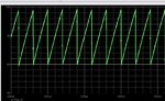
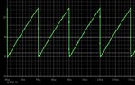
so , as you can see at top , pictures , the first one is the out put wave that is from across the c2 . it is a sawtooth wave .
and about picture number two :
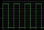
it is my input wave . an square wave .
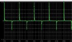
And about picture number three it is differential from input square wave ! are you confused about this ??!! no problem i'll tell you the reason of this event , be patient !
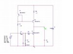
and about picture number four :
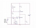
it is the circuit of these wave forms !
Discussion and design step by step :
i created a current source that consists from Q3 and Q2 and R4 and R1 . if we neglect from R4 the current will given by : (V1-0.6)/R1 simply .
and differentiator network that consists from D3 and C1 and R3 . it will take differential from our input waveform , and i used D3 to prevent breaking BE junction instead of negative voltage that is about 5 volt .
and R2 is used to decrease the base current to prevent damages to it's junction .
if you probably understood , if Q1 is off , the capacitor is going to be charge . and if Q1 be turn on it will be discharge .
And about why , i used that differentiator :
If duty cycle of input wave change , it will affect on out put wave directly .
Or it is possible that , out put wave won't be full wave .
so i used that differentiator , because at zero point , it can give command of discharge and thus the problems that i told at top doesn't matter .
So , come on to design a circuit with our hands !
for example we want a sawtooth wave with frequency about 50 KHZ and it's amplitude about 10 volts .
find the value of parameters .
Solution :
because the current of capacitor is linear ( not exponential ) ( because we used a current source to supply our capacitor )
so we should use from this formula :
Ic=C*dvc/dt ------> Ic*dt= C*dvc ----> both side divide by C ----> 1/c Ic dt = dvc -----> take an integral from both side of this equation :
---------> vc= 1/c integral over Ic dt . from zero up to T ( because at the star time of each pulse it will give the command of discharge )
and after solving this equation , we will have :
Ic =VC*C/T
so it will be the main formula that we want .
And let come back to the required circuit : we can select a capacitor randomly e.g 10 nf , then we will have :
Ic =(10*10^19)*10/20 usec ------> Ic =5 ma
So we should make our current source to provide 5 ma at maximum mode . as i mentioned at past : I= (Vcc-0.6)/R1
So how much should be the value of VCC ? with a simple approximation for design we can say , that it should be about 40 percent more than out put voltage so vcc will be about 14 volts . and R1=(14-0.6)/5*10^-3 -----> R1 = 2.7k ohms ( approx) .
And about differentiator network design :
C1*R3 should be about 1/12 PW and if the duty cycle of input wave be 50 percent the PW , surely will be about 10 usec
And (1/12)10usec=833nsec -------> we can select a capacitor for C1 randomly , and then R3 will given . e.g 300 pf -----> R3= 2.7k ( approx) .
Ok our circuit is ready to use but we'de better to use a low value resistor at emitter of Q2 ( between 10 ohms and 5.6 ohms ) to obtain better precision at current and surely the out put wave without DC voltage ( we can select that resistor until the out put wave has zero point (if you don't put that resistor the out put wave will shift to the top )(because as we know the precision of current mirror will increase by adding a resistor at emitter of Q1 , and as we know this current source called widlar current mirror ) )
see the result of simulations :


If you have any problem , ask me , please , i'll be happy to answer your questions .
Good luck
Goldsmith
Hi
I came back again , with some good things !
And if you see i don't write all things at one , blog , the reason is that i want you think about things that i write carefully .
Before that , let me appreciate from "LvW" and "FvM " and "syncopator " , because of their friendly helps to me .
Anywhere , for PWM , if we don't want use ne555 or some other integrated circuits , ( because of some reasons ...) we will have a best way to create sawtooth wave from an square wave .
see below , please :
so , as you can see at top , pictures , the first one is the out put wave that is from across the c2 . it is a sawtooth wave .
and about picture number two :
it is my input wave . an square wave .
And about picture number three it is differential from input square wave ! are you confused about this ??!! no problem i'll tell you the reason of this event , be patient !
and about picture number four :
it is the circuit of these wave forms !
Discussion and design step by step :
i created a current source that consists from Q3 and Q2 and R4 and R1 . if we neglect from R4 the current will given by : (V1-0.6)/R1 simply .
and differentiator network that consists from D3 and C1 and R3 . it will take differential from our input waveform , and i used D3 to prevent breaking BE junction instead of negative voltage that is about 5 volt .
and R2 is used to decrease the base current to prevent damages to it's junction .
if you probably understood , if Q1 is off , the capacitor is going to be charge . and if Q1 be turn on it will be discharge .
And about why , i used that differentiator :
If duty cycle of input wave change , it will affect on out put wave directly .
Or it is possible that , out put wave won't be full wave .
so i used that differentiator , because at zero point , it can give command of discharge and thus the problems that i told at top doesn't matter .
So , come on to design a circuit with our hands !
for example we want a sawtooth wave with frequency about 50 KHZ and it's amplitude about 10 volts .
find the value of parameters .
Solution :
because the current of capacitor is linear ( not exponential ) ( because we used a current source to supply our capacitor )
so we should use from this formula :
Ic=C*dvc/dt ------> Ic*dt= C*dvc ----> both side divide by C ----> 1/c Ic dt = dvc -----> take an integral from both side of this equation :
---------> vc= 1/c integral over Ic dt . from zero up to T ( because at the star time of each pulse it will give the command of discharge )
and after solving this equation , we will have :
Ic =VC*C/T
so it will be the main formula that we want .
And let come back to the required circuit : we can select a capacitor randomly e.g 10 nf , then we will have :
Ic =(10*10^19)*10/20 usec ------> Ic =5 ma
So we should make our current source to provide 5 ma at maximum mode . as i mentioned at past : I= (Vcc-0.6)/R1
So how much should be the value of VCC ? with a simple approximation for design we can say , that it should be about 40 percent more than out put voltage so vcc will be about 14 volts . and R1=(14-0.6)/5*10^-3 -----> R1 = 2.7k ohms ( approx) .
And about differentiator network design :
C1*R3 should be about 1/12 PW and if the duty cycle of input wave be 50 percent the PW , surely will be about 10 usec
And (1/12)10usec=833nsec -------> we can select a capacitor for C1 randomly , and then R3 will given . e.g 300 pf -----> R3= 2.7k ( approx) .
Ok our circuit is ready to use but we'de better to use a low value resistor at emitter of Q2 ( between 10 ohms and 5.6 ohms ) to obtain better precision at current and surely the out put wave without DC voltage ( we can select that resistor until the out put wave has zero point (if you don't put that resistor the out put wave will shift to the top )(because as we know the precision of current mirror will increase by adding a resistor at emitter of Q1 , and as we know this current source called widlar current mirror ) )
see the result of simulations :
If you have any problem , ask me , please , i'll be happy to answer your questions .
Good luck
Goldsmith
 I want to share you some simple...