Generally people use ISP (In System Programming) when it comes to micro controllers with flash memory.
One of the basic software for such purpose is FLASH MAGIC .
But every single person who has ever used flash magic knows it never works the very first time and the frustration goes on building up.Here is a small step by step guide :
1. Make sure the power on the board to be programmed is switched off.
2. Make sure the jumper is in the ISP position.
3. Connect serial cable from PC into the serial connector on the board to be
programmed.
4. Turn the power on to the board to be programmed.
5. Start Flash Magic.
6. If this is the first time using this program it will need to be set up. Set the COM
port to the serial port connected to the board to be programmed, Baud Rate to
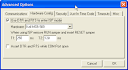
9600, select your device . Go to Options>Advanced Options…and click on the
Hardware Config tab. Make sure the check box is checked so the program will
use the DTR and RTS lines to enter ISP mode. Click OK on the messages and to
close the dialog box.
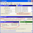
7. Flash needs to be erased before it can be reprogrammed. Highlight the blocks to
be erased in step 2 in the Flash Magic Program. You can also check the box
marked “Erase blocks used for Hex File.” Do not erase the entire chip or block 7.
Block 7 contains the ISP program. If it is erased, we will not be able to reprogram
the microprocessor.
8. Browse for the file to be programmed into the board.
9. In step 4, nothing needs to be set. Do NOT enable the security bits. This will
disable the access to the ISP.
10. Click on Start.
11. If the board fails to establish communication, then check the following: a) If IC6
is installed it may interfere with communication, carefully remove it using a small
screwdriver to pry it up b) Make sure the jumper is in the ISP position c) Check
the serial cable (If you are using a “null modem” cable the pin one connection can
cause a short. Cut the trace between pin 1 and pin 7 on the 9-pin connector of the
embedded computer board) d) Check the settings on Flash Magic e) Make sure
power to the embedded board is turned on.
12. After the board has been programmed, the status bar in the lower left hand corner
will display finished. The board can be turned off and disconnected from the
serial cable. Move the jumper from ISP to RUN.
13. Turn the board on to execute its program.
One of the basic software for such purpose is FLASH MAGIC .
But every single person who has ever used flash magic knows it never works the very first time and the frustration goes on building up.Here is a small step by step guide :
1. Make sure the power on the board to be programmed is switched off.
2. Make sure the jumper is in the ISP position.
3. Connect serial cable from PC into the serial connector on the board to be
programmed.
4. Turn the power on to the board to be programmed.
5. Start Flash Magic.
6. If this is the first time using this program it will need to be set up. Set the COM
port to the serial port connected to the board to be programmed, Baud Rate to
9600, select your device . Go to Options>Advanced Options…and click on the
Hardware Config tab. Make sure the check box is checked so the program will
use the DTR and RTS lines to enter ISP mode. Click OK on the messages and to
close the dialog box.
7. Flash needs to be erased before it can be reprogrammed. Highlight the blocks to
be erased in step 2 in the Flash Magic Program. You can also check the box
marked “Erase blocks used for Hex File.” Do not erase the entire chip or block 7.
Block 7 contains the ISP program. If it is erased, we will not be able to reprogram
the microprocessor.
8. Browse for the file to be programmed into the board.
9. In step 4, nothing needs to be set. Do NOT enable the security bits. This will
disable the access to the ISP.
10. Click on Start.
11. If the board fails to establish communication, then check the following: a) If IC6
is installed it may interfere with communication, carefully remove it using a small
screwdriver to pry it up b) Make sure the jumper is in the ISP position c) Check
the serial cable (If you are using a “null modem” cable the pin one connection can
cause a short. Cut the trace between pin 1 and pin 7 on the 9-pin connector of the
embedded computer board) d) Check the settings on Flash Magic e) Make sure
power to the embedded board is turned on.
12. After the board has been programmed, the status bar in the lower left hand corner
will display finished. The board can be turned off and disconnected from the
serial cable. Move the jumper from ISP to RUN.
13. Turn the board on to execute its program.