Continue to Site

Welcome to EDAboard.com

Welcome to our site! EDAboard.com is an international Electronics Discussion Forum focused on EDA software, circuits, schematics, books, theory, papers, asic, pld, 8051, DSP, Network, RF, Analog Design, PCB, Service Manuals... and a whole lot more! To participate you need to register. Registration is free. Click here to register now.

Where do I get a ground from in this circuit?

Status
Not open for further replies.

zaph1

Junior Member level 1
Joined
May 28, 2010
Messages
19
Helped
3
Reputation
6
Reaction score
0
Trophy points
1,281
Location
Altoona, Iowa
Activity points
1,422
AnodizerSchematic.gif


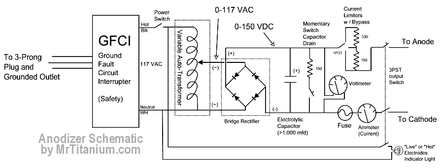
I'm working with the above schematic to make a variable DC voltage power supply. I want to add a couple voltage regulators to provide 12vdc for a cooling fan and 5vdc for the 4 digit display I have. My understanding is that I can use the +/- signals from the rectifier to input to the regulators. However, I need a ground. Where do I get the ground from? Green wire from the AC input? Or, is the ground for DC different than ground for AC?
 

Once you have gone through the bridge rectifier the AC & DC grounds are not the same. Use the negative out from the bridge as your DC ground.

Keith
 

You can't feed voltage regulators by 150 V DC. You better should use a small 117 to e.g. 12 V transformer. You may want to isolate
the DC low voltage supply from the high voltage circuit. It actually don't need a "ground", just keep it floating.
 

Ok, I'm confused. Do I take the negative signal to both the input and ground pin on the negative regulator?
 

This is the connection I think your are wanting:


The input "ground" is not the same as the output "ground" - there is a diode between them.

As has been pointed out by FvM - regulators usually only take 30V to 40V maximum input, so you need another arrangement really.

Keith.
 

I think the real answer is if you connect a ground, either to the incoming AC socket or to a ground rod, you are likely to trip the ground fault interrupter. There is no real 'ground' as the whole circuit is floating and not isolated from incoming AC. Make sure you have a polarized AC plug as well as reversing it will swap your neutral and hot connections.

If you mean 'where can I use as a reference point to measure from', the negative side of the bridge rectifier is a good place.

Be very careful with this circuit, it is not inherently safe and you run the risk of electrocution, even with the transformer voltage set to minimum. Connecting it to other equipment, which I guess is why you want to use the regulators, will almost certainly be unsafe. Also heed the warning about voltage fed into the regulators, even if you can find a 150V to 12V regulator, please bear in mind it will dissipate 138W of heat for each Amp you draw from it !!

Brian.
 

I hope everyone had a pleasant Memorial Day Weekend.

This is being used as a Titanium anodizer power supply. Titanium needs 20-130v at low amperage to anodize. The amperage should be around 100ma. I was trying to find a way to power the fan at 12vdc, but I can easily swap it with a 120vdc fan. Buying special regulators will negate the purpose and it would be cheaper to get the AC fan instead.

Now, about the multimeter, I still need +5vdc and 0vdc. I can strip out a transformer from a plug-in unit, but it will be bigger and hotter than what I need, around 50ma. Any suggestions on the best way to get this without the clutter of a stripped wall transformer?
 

Hi Zaph,
I remember that it did exsist HV-version of LM317 or 740?
In that case was input up to ca. 150V possible, search pls by National Apps/datasheets...
But Im wondering, that your anodiser is NOT AC ISOLATED!? :-(
Has it a bath too? (I dont know the technology...)
Good Weekend!
K.
 

Wow, I'm not exactly sure how I would convert this circuit to be isolated. Could you expand on that?

Yes, there is an electrolyte bath that the metal is in.
 

Hi,
The simplest way is, in my opinion, to change the variac.autotransformator to an isolated variac!
K.
 

Hi Zaph,
I found the HV-version circuit of LM317, hope that helps for you...
K.
 

OK, getting too complicated that route. Maybe I could just use a transformer hooked to the 120VAC to get the signal.

I started building and testing it today. I get a nice .5vdc - 108.1vdc after the rectifier.
Here's where I am afraid I am going to blow something up. According to the schematic, the capacitors are spliced into the +/- and not actually inline. Is this correct, or should they be inline? The same for the resistor. Does it simply go across from the negative to the positive with a momentary switch activating it?
 

Status
Not open for further replies.

Similar threads

Part and Inventory Search

Welcome to EDABoard.com

Sponsor

Back
Top