Continue to Site
Follow along with the video below to see how to install our site as a web app on your home screen.
Note: This feature may not be available in some browsers.
Hi everyone,
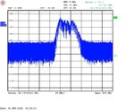
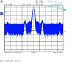
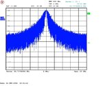
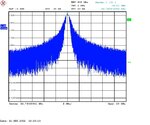
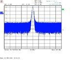
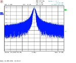
The PLL output spectrum seems abnormally wide as shown in the attachment. It's a 20 GHz PLL design with 92 MHz reference and 256 divider-N. Can anyone tell me the potential reason?
Thanks,
Hi everyone,
The PLL output spectrum seems abnormally wide as shown in the attachment. It's a 20 GHz PLL design with 92 MHz reference and 256 divider-N. Can anyone tell me the potential reason?
Thanks,
The spectrum is just as abnormal at open loop, i. e. applying a fixed DC voltage to the control input of the VCO?. If yes, then you are having a low frequency quenching on the oscillator, as in old superregenerative receivers. Decouplings, couplings time constants, strength of positive feedback and DC bias components may have an influence on this.
- - - Updated - - -
Another hint: if the VCO is clean by itself, please check the prescaler input level. If too low, it may be dividing by an erratic value instead of the intended N. Many prescaler topologyes self-oscillte if poorly driven.
I cannot see any attachment, but an "abnormally wide" output spectrum from such PLO like yours can have two basic sources:
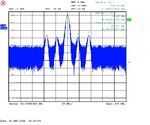
a. out of lock, the PLO is "searching", and the wide spectrum has narrow distances between the lines which change by spectrum analyzer setting. Check the reference signal power, frequency and stability.
b. interference on DC power line (or in the reference line), coming often from a switching C power supply and /or voltage regulator. For PLO's, use preferably a linear power supply, and check the voltage with a scope. Any interference with a voltage > 30-50 mV p-p can drive the phase noise high.
I used similar structures locked from references like yours, without problems. The only other than the nominal output frequency should be spaced by the reference (or reference divided) frequency. My PLOs used a multiplied reference; using a divider may complicate the optimum function.
- - - Updated - - -
I cannot see any attachment, but an "abnormally wide" output spectrum from such PLO like yours can have two basic sources:
a. out of lock, the PLO is "searching", and the wide spectrum has narrow distances between the lines which change by spectrum analyzer setting. Check the reference signal power, frequency and stability.
b. interference on DC power line (or in the reference line), coming often from a switching C power supply and /or voltage regulator. For PLO's, use preferably a linear power supply, and check the voltage with a scope. Any interference with a voltage > 30-50 mV p-p can drive the phase noise high.
I used similar structures locked from references like yours, without problems. The only other than the nominal output frequency should be spaced by the reference (or reference divided) frequency. My PLOs used a multiplied reference; using a divider may complicate the optimum function.
- - - Updated - - -
Now I can see the picture: it is a typical "out -of-lock" situation. Try to tune the microwave oscillator till it locks. If it does mot, check my answer a. above.