Continue to Site

Welcome to EDAboard.com

Welcome to our site! EDAboard.com is an international Electronics Discussion Forum focused on EDA software, circuits, schematics, books, theory, papers, asic, pld, 8051, DSP, Network, RF, Analog Design, PCB, Service Manuals... and a whole lot more! To participate you need to register. Registration is free. Click here to register now.

[SOLVED] What voltage does my four wire motor need for the stator and brushes 100/50 stamped on motor

Status
Not open for further replies.

crysotyle

Junior Member level 2
Joined
Feb 9, 2020
Messages
21
Helped
2
Reputation
4
Reaction score
0
Trophy points
1
Activity points
192
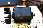
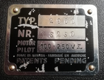
I have a motor on a 1930's projector, the plate on the projector says 100 - 250 v AC and DC, the motor has stamped on it 100/50 and has four wires two for the brushes and two for the stator. I have tested the motor on an old laptop supply which puts out 19v DC and it worked great, albeit a bit slow. What voltage is needed on both the Stator and the Brush wires to make it run correctly. Both the stator and the brushes were wired to the 19v DC. The motor is revisable which worked when tested.
 

Attachments

  • IMG_20210102_142742.jpg
    IMG_20210102_142742.jpg
    1.5 MB · Views: 213
  • IMG_20210103_121840.png
    IMG_20210103_121840.png
    398 KB · Views: 203

The motor appears to be a reversible universal motor. It can work on DC and AC (does not matter but the frequency should not be too high).

To run on 110V (DC or AC), put the rotor and stator in parallel. To make it for 220V, put the rotor and stator in series.

To reverse the motor, reverse one of the coils.

The no-run DC resistances of the rotor and stator should not be too different. Test with a regular multimeter.

Do you have some idea about the power? It should be written somewhere (else you need to guess from the weight).
 
I did attach the plate from the projector, its below. The projector was designed to run on 250/200, 160/140 or 120/100 volts and has resistor used to vary the speed of the motor as well. It also has a circuit with to low voltage (12v maybe) bulbs in to give some light when threading the film. I'm only trying to get it working on 240v side. It has a switch to revers the direction of the motor. The motor has 100/50 stamped into the casing.


IMG_20210103_121840.pngIMG_20210103_163631.png
 

Motor cannot run on 12V and 250V without modification. As the boilerplate says that the motor is supposed to run on 250V, it should run without the external resistor. As the motor is relatively low power, you should be safe to connect the two windings in series and run safely on 250V. To be on the safe side, run the motor outside (and monitor the temp rise) before putting it back. The power resistor may be used to adapt the voltage for the lamp (did you measure the resistance of the nichrome coil with a multimeter?)
 

    crysotyle

    Points: 2
    Helpful Answer Positive Rating
The 12v is for the main light and the pilot lights, not the motor. I'm changing the bulbs on the projector as they are no longer made and can cost between £30 to £60 each, if you can get one at all, changing to 12v 50w halogen and 12v 0.6w MES type for the pilots, this will run from the 240v supply through a transformer of some sort. Really need the project motor speed to vary as the speed of the film needs to change depending on the film format used. The resistor is measuring 0.38 when set to 20K on the meter. Below is another part of the electrics I have removed, this is the board where the voltage selection is made.

IMG_20201227_154834.png
 

I see.

The main motor voltage selection is done by the series (for 250V) or by parallel (for 110V) combination of the stator and rotor windings. They coils (static values) will have about the same resistance when measured by a regular multimeter. Reversing the motor can be done interchanging one of the coils (exchange the terminals; most easily done with a DPDT switch).

The rheostat may be used for fine tuning the speed of the motor. I guess the motor runs on a constant load and the speed can be regulated by the voltage. I notice a central ring on the rheostat - it should be movable and provided with a lug for connection.

There are 12V 5A modules available that run off the mains and can be cheaper and better than a regular transformer. Based on the series resistance used for the speed control, I guess the motor power to be around 30-50W.
--- Updated ---

1. I could not make out the connection pattern on the photo in post #5.

2. If you are going to use a 50W halogen lamp do not forget to install a small fan close by. A 12V fan in parallel with the lamp will be a good choice. Some fans tend to be noise-some so choose the fan wisely.
 
Last edited:

    crysotyle

    Points: 2
    Helpful Answer Positive Rating
Picture 5 is not a Rheostat it looks like one but has no moving parts, I think it is a choke, not going to use because of the state of it.

I plan to remove the bulb from the holder, picture 1, install a 240v to 12v transformer with the 12v bulb above it, in the space, in line with the lenses and also drive the 12v 0.6w pilot bulbs from it. The space is tight but the fan on the motor blows through and past this area. I have found some small chassis mount transformers and toroidal and it has been mentioned I could use switched power supplies but they are all tight, might not fit. have you any ideas on some thing smaller. What is the 12v 5A unit you mention above.

I have two Rheostat I plan to use the first as the resistance is closer to the one for the motor.

The motor is going to be wired like the image, this is how I tested it, do you see any issues with this at 240v


IMG_20210104_190356.jpg
IMG_20210104_185918.jpg
motor wire diagram.jpg
 

Picture 5 is not a Rheostat it looks like one but has no moving parts, I think it is a choke, not going to use because of the state of it.

It is certainly not a choke, because this is not likely to have any usable inductance at 50/60Hz. Also the resistance is likely to be useful for speed adjustment. Anyway, if you are not going to use it, fine but you will need a way to fine tune the speed of the motor because projector motors should have a regulated speed.

The motor is going to be wired like the image, this is how I tested it, do you see any issues with this at 240v

You are wiring the coils in parallel; for 220/240V, the coils need to be used in series. Connect 2 and 4 and apply voltage across 1 and 3. You may use a 200 Ohm theostat in series with the mains that can be used for speed control.

100V-250V input /12V DC output at 5-8A modules are widely available. I saw a few on Aliexpress. You can search yourself. Modern 50W halogen lamps are smaller and hotter and brighter. You can run them at 10-11V for a long life (regulated DC voltage helps considerably). A small fan directly blowing on the lamp can be very effective.
--- Updated ---

One module I found on Aliexpress: https://www.aliexpress.com/item/100...=a2g0o.store_home.smartJustForYou_488398248.4
 
Last edited:

    crysotyle

    Points: 2
    Helpful Answer Positive Rating
Hi,

Thanks for more info. I have now built a little test, rig as wanted to test on 240v its a bit safer. I have tried this on both 240 and 110v with two different rheostats of different resistance. I'm not happy with any of the configuration as either the rheostats appear to run to hot or the motor runs to fast, this was true for both voltages. the bottom rheostat in white is almost exactly the same resistance of the wire wrapped one #3 but get very hot. Wire one and two are connected as was originally to the revisable switch. the other switch is just the on off. Feels like there is to much power getting to the motor and or in the circuit.

I have added a closeup shot of the thing that looks like a rheostat, it has no moving parts and has a single bolt holding it to the board, there are two separate coils of wire each coils looks like a single piece of wire they are not connected to each other. Looks like some sort of resistor like the tube ones with wire wrapped around them in the picture at #3 could this be some thing to do with to much voltage/current?

Any thoughts?

IMG_20210109_144546.pngIMG_20210109_144900.pngIMG_20210109_095040.pngIMG_20210109_164643.jpg
 

By happenstance I have similar rheostats which work like a potentiometer (if I follow your description correctly). All locked in place by a nut. Despite loosening the nut it requires that I apply force from a large screwdriver to turn.

0109211238.jpg


By dialing it to the middle position you can utilize the entire wire, thus turning it into two parallel wires at 1/2 the labelled resistance. Resulting power rating is greatly increased.
 

Yes, It is clearer now.

The reversing switch is a regular DPDT switch arranged like Pohl's commutator.

Good that you have labeled the wires. The four end contacts are cross connected and you have effectively four wires connected.

I am not able to understand the connections. 110V connection, as seen in the first two diagrams, appears correct.

1,2 are connected to the commutator. I think the connection is not shorted. Please check.


The wave wound coil is a choke; but it looked black and burnt. It also should have been in series with the rheostat. The choke is made of two sections.

Do you have four terminals or two terminals coming from the choke?

Does the choke has a iron core (check with a magnet) inside?

These rheostats are supposed to get hot (but check is the base is ceramic or not).

Is the motor running very hot? Can you test the motor at 24V DC (it is it running at a decent speed).

If yes, then you can also use a fluorescent tube choke (meant for 40W tube at 110V AC) in place of the old choke.

What was the original mode for adjusting the motor speed?
 
Last edited:

The 240v 110v connections are just there so that I can switch between them more easily, as I have a 110v transformer on a USA type plug and a standard UK plug for the 240v.

Connection 1,2 are to the commutator and 3,4 are the stator, I have completed a continuity test between the body of the motor and the 1,2,3,4 wires and all passed, no current passes between them and the body of the motor.

The each choke coils has two wires and they are mounted on a hollow tube they are not connected to each other see image.

Both of the chokes seem to be on some sort of ceramic.

The motor is not running hot, it is running to fast particularly as I reduce the resistance on either rheostat.

I assume the missing choke will slow down the motor.

#3 the second picture shows the motor speed adjuster, the pivoting arm slides along the wire wrapped ceramic tube, I have added a new picture of it.

I would also need to introduce a capacitor into the circuit.


IMG_20210110_111450.pngIMG_20210110_120539.png
 

Right.

These motors do not have a fixed speed; they run at a speed that depends on the applied voltage. For 110V use, you are using it as a shunt wound and for 220V use, you are using it as series wound (see wikipedia for a description of shunt and series winding motor). You are using reversing the connection to reverse the motor. I consider the setup is correct.

1. These motors run high speed and the speed reduces under load. If the motor is running cool, there is nothing to worry.

2. The choke is black; inspect carefully whether it is burnt (insulation damaged).

3. The motor appears big in size but the power needed is small; can you please report the DC resistance of the stator, rotor and the rheostats.

4. Was there any capacitor along with the choke? Was it for noise suppression?

5. What are the power ratings of the rheostats?
 

I have not run the motor for any long periods at the moment, as when things get hot I turn everything off. not confident the setup is quit right yet. The components of the projector are not easily replaceable if I break or burn them out.

The choke is black because it is full of oil and dirt from years of oil dropping on it from the 1930-40s to today, cine projectors need greasing and oiling to keep them running, this is why everything is covered in oil and dirt after 80-90 years of use. I can't use the old choke, I have tested, there is no continuity through either coil and I get no change on the meter when testing the resistance.

0.044 on the commutator, 0.024 on the stator with tester set to 2k. The top brown rheostat is 0.15, the bottom white one is 0.82 on first image on #9 and the original tube one from the projector image 2 on #3 is 0.38 with the tester set to 2k.

There was a three legged capacitor in place which was I think used for noise suppression between live and neutral on the motor.

Not sure of the power ratings of any of the rheostats, can't see anything marked.

IMG_20210110_144036.jpg
 

The resistance values appear typical. The motor appears in good health. I cannot make out the significance of the number printed 100/50.

The choke is most likely designed for noise filtering. You can substitute any commercial LC filter for 110/220V AC mains use. Such modules are common although it is not needed for the operation of the equipment.

Remember that the speed need to set with the machine running. Without load, the motor will run vast, very fast (20-30k RPM) and setting the speed without the load is meaningless.

Be careful because you will be dealing with mains voltages. Do not try to adjust speed with the power on; the power switch used works on one line only. So, pull out the plug! I know it can be frustrating but it can be done with safety.
 
Nearly there getting it wired up have the switched mode power supply now, and getting a new DPDT switch.

In #14 I made a mistake with the resistance values the numbers are right, but the tester was set to 20k so I'm now confused about the Ohms values, trying to find the rheostat to replace the the slide rheostat in #12. It's OHMS resistance is 0.38 the wire size is 0.20 mm 284 turns ish.

Can't find the right rheostat because none of the ohms seem to match and not sure what current would flow through the old slide rheostat. how do I know the current needed for the motor, could the 100/50 mean something on the motor could it be the wattage.
 

So if the resistance is 0.380 ohms with the meter set to 2K I get 760 ohms. 0.380 x 2000 = 760
 

So if the resistance is 0.380 ohms with the meter set to 2K I get 760 ohms. 0.380 x 2000 = 760

I doubt your reasoning.

Meter set to 2K range means that the max the display can show is 1999. It has a 3 1/2 display (one digit can show max 1 and the remaining 3 digits can show upto 9). Therefore all ranges will show as multiples of 2x10**(n); i.e., 2, 20, 200, 2k, 20k, 200k etc. These are the max values the meter can show.

Most likely your meter will have 2, 2k and 2m ranges. But why waste time? just test with a regular 120R or 1k resistor and verify the value with the printed or color band reading.
 

Will try what you suggest, thanks so much for your help with all the above.
 

Status
Not open for further replies.

Similar threads

Part and Inventory Search

Welcome to EDABoard.com

Sponsor

Back
Top