Continue to Site

Welcome to EDAboard.com

Welcome to our site! EDAboard.com is an international Electronics Discussion Forum focused on EDA software, circuits, schematics, books, theory, papers, asic, pld, 8051, DSP, Network, RF, Analog Design, PCB, Service Manuals... and a whole lot more! To participate you need to register. Registration is free. Click here to register now.

Viper22 based SMPS circuit

Status
Not open for further replies.

UroBoros

Advanced Member level 2
Joined
May 5, 2004
Messages
642
Helped
19
Reputation
38
Reaction score
8
Trophy points
1,298
Location
Cochin - India
Activity points
6,463
Re: Viper22 based SMPS circuit and design Tools

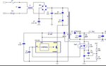
This sis a viper22 based application note circuit I am trying to make.

On power up nothing happens- luckily nothing burns at least visually.
The chip seems not oscillating. no voltage except 300VDC across drain and source. Some 2.5 volts is shown at Viper22 VCC pin.

I wound the transformer following the dot rule.(I believe it is correct). tried by exchanging connections of transformer.
Please suggest how should I zoom into the problem. I have a multimeter, and a PC based DSO. Will arrange an isolation transformer also.

Please
 

Attachments

  • viper22.JPG
    viper22.JPG
    38.5 KB · Views: 1,866
Last edited:

Re: Viper22 based SMPS circuit and design Tools

change the viper22 and try

No effect. Either Viper22 is silently blowing up the moment I switch on, or something else is wrong.

The chief suspect may be transformer.(?)

I have no experience in SMPS - So please.

1. If the transformer winding and inductance is not proper what will happen? The circuit will not start or , will start with wrong voltages and specifications?

This is SMPS design tools for Viper and Fairchild switcher ICs. These tools are now not to be found in the .exe form in their web sites now. (Correct me if wrong!)
Hope it may be useful.

Code:
http://rapidshare.com/files/436595281/smpsdesignTools.zip

Thanks
 

Re: Viper22 based SMPS circuit and design Tools

The chief suspect may be transformer.(?)
1. If the transformer winding and inductance is not proper what will happen? The circuit will not start or , will start with wrong voltages and specifications Thanks
Yes..the transformer inductance must me exactly the same as specified by the manufacturer or as result generated by the simulator. Or the frequency will shift resulting in harmonics with output resulting in wrong volatges aprat from what it is designed for. The airgap between the cores too counts in this regard.
Cheers
**broken link removed**
 

According to my paractical experience, problem will not because of the transeformer. i have a power supply with same problem and give me few days i will give the answer.

---------- Post added at 21:06 ---------- Previous post was at 19:41 ----------

1.1.1 Start-up Phase
As any member of the VIPer family, VIPer22A has an integrated high voltage current source linked to
Drain pin. At the startup converter, it will charge the VDD capacitor until it reaches VIPer startup level
(14.5V), and then the VIPer22A starts switching.
1.1.2 Auxiliary Supply
VIPer22A has a wide operating voltage range from 8V to 42V, respectively minimum and maximum
values for under-voltage and over-voltage protections.
This function is very useful for achieving low stand-by total power consumption. During normal working,
the feedback loop is connected to 5V output by D12 to regulate 5V output. At the mean time, +5Vstb
output is blocked by Q3, so +5Vstb regulation is neglected. When the stand-by signal is present, the Vce
of Q3 can not provide enough voltage to maintain D12 conducted, so the 5V output is blocked, and the
+5Vstb output is connected to the feedback loop. In this condition the +5Vstb is regulated. Thanks to the
transformer structure, all the other secondary outputs and the auxiliary voltages are pulled down to a very
low level, also pulling down the total power consumption.
All these contents can be summarized by the following list:
· in normal full load, the VDD voltage of the device must be lower than the over-voltage protection;
· in short circuit, the VDD voltage must be lower than the shutdown voltage. Actually, this condition leads
to the well known hiccup mode in practice;
· in no load condition, the VDD voltage must be higher than the shutdown voltage.


---------- Post added at 21:06 ---------- Previous post was at 19:41 ----------

1.1.1 Start-up Phase
As any member of the VIPer family, VIPer22A has an integrated high voltage current source linked to
Drain pin. At the startup converter, it will charge the VDD capacitor until it reaches VIPer startup level
(14.5V), and then the VIPer22A starts switching.
1.1.2 Auxiliary Supply
VIPer22A has a wide operating voltage range from 8V to 42V, respectively minimum and maximum
values for under-voltage and over-voltage protections.
This function is very useful for achieving low stand-by total power consumption.

· in normal full load, the VDD voltage of the device must be lower than the over-voltage protection;
· in short circuit, the VDD voltage must be lower than the shutdown voltage. Actually, this condition leads
to the well known hiccup mode in practice;
· in no load condition, the VDD voltage must be higher than the shutdown voltage.

One simple solution to avoid "hiccup" and "no start" is to shunt the output with a resistor, to provide a load. A typical value could be about 250 ohms (1W) for a 5 V output.
 

Status
Not open for further replies.

Similar threads

Part and Inventory Search

Welcome to EDABoard.com

Sponsor

Back
Top