Continue to Site

Welcome to EDAboard.com

Welcome to our site! EDAboard.com is an international Electronics Discussion Forum focused on EDA software, circuits, schematics, books, theory, papers, asic, pld, 8051, DSP, Network, RF, Analog Design, PCB, Service Manuals... and a whole lot more! To participate you need to register. Registration is free. Click here to register now.

Trying to repair an RF generator

Status
Not open for further replies.

alphamike

Newbie
Joined
Apr 17, 2021
Messages
3
Helped
0
Reputation
0
Reaction score
0
Trophy points
1
Activity points
37
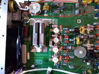
I am trying to understand how RF power generators are designed so that I can try to fix a problem with my Seren 600W RF generator (13.56MHz). I could not find much information on what is inside these generators. Looking at the circuit board, it appears to be an oscillator circuit followed by a power amplifier and some filters. What I don't know is how the output power and reflected power are being measured.
This RF generator is having intermittent problems. The forward power suddenly drops from the set value (lets say 100W) to something very small, like 5W. After a reset, it seems to work fine for a little while, and then the problem begins again. I am trying to understand where the problem might be.
 

Possible thermal cooling problem, eg. a fan not kicking on, thermal grease
no longer functional (if solid state PA). Even a bias circuit fed by a regulator
that is getting hot....

Regards, Dana.
 

I've gotten used thermal test equipment that
would shut down and vent unexpectedly,
turned out the heat exchanger fins were
matted with 1/2" of some sort of "hair". Did
not become obvious until I started pulling
the side panels off the rack.
 

When the power drops, I am able to give it a sharp snap on the side and it comes back on, for a few more seconds. That suggests something mechanical, but I don't see anything loose inside, or bad solder joints.
 

I don't know what Seren model you have, but the one presented in the manual below shows that the device needs an antenna tuner at the output (AT matching network, at page 47):

Without this antenna tuner if you do not provide the right load impedance at the output of the amplifier (usually 50 ohms), this will go in SWR protection mode.
 

Thanks for all the suggestions. I narrowed it down to a problem with the reflected power sensor. Occasionally, it is detecting a very high reflected power (100W) and it is going into protective mode by dropping the forward power. However, I don't believe this measurement is real. With 5W power, it is showing a 50W reflected power. With 10W, it is showing a 100W reflected power. So it is about 10x of the forward power. Since 100W is the maximum allowed reflected power, I am being limited to 10W forward power. The issue is that this happens only some times. At other times, it works fine (i.e I can put 50W and it shows a very low reflective power). There is something flaky with the reflected power sensor, and since I don't fully understand how reflected power is being measured, I am poking around the circuit board looking for clues. Attached is an image of the board. The top left corner is the output, and I think the circuit next to it is the forward/backward power sensor.
 

Attachments

  • IMG_20210417_224015769.jpg
    IMG_20210417_224015769.jpg
    339.1 KB · Views: 179

Can we see the load that you are using for these measurements?
 

If banging it sometimes fixes the problem and the reflected power is changing I would point my finger at the output connector or wiring to it.

Brian
 

high power amplifiers are their own special beast. the picture does not tell us much, other than there are 4 high power FET transistors in parallel generating the 600 watts.

at this power level, something might have burned out. A directional coupler at these frequencies would be some sort of lumped element thing with a ferrite and windings on it. a capacitor might have microcracked, and works fine until it heats up, then becomes an open circuit. a solder joint might have let loose. a detector diode might have blown up, and so on.

With the RF power off, there might be a way to inject a smaller signal back into the output port, and see if the reverse power detector is actually detecting power. Somewhere there is a circuit in there that converts reverse power into voltage, and you could measure that circuit.

you will have to contact the manufacturer for an operating manual, that hopefully has a schematic diagram in it. get that, and tell us what the reverse power detector portion looks like.

btw, there is probably a pretty high drain voltage on those output fets--no touch!!!
 

Status
Not open for further replies.

Similar threads

Part and Inventory Search

Welcome to EDABoard.com

Sponsor

Back
Top