Continue to Site

Welcome to EDAboard.com

Welcome to our site! EDAboard.com is an international Electronics Discussion Forum focused on EDA software, circuits, schematics, books, theory, papers, asic, pld, 8051, DSP, Network, RF, Analog Design, PCB, Service Manuals... and a whole lot more! To participate you need to register. Registration is free. Click here to register now.

The concept of introducing delay line in a radar system

Status
Not open for further replies.

luckyali

Member level 5
Joined
Jun 6, 2011
Messages
84
Helped
2
Reputation
4
Reaction score
2
Trophy points
1,288
Location
Germany
Activity points
1,966
hi friends, a new issue to be discussed.
I was reading about ultra wide band radar sensors. and found a nice block diagram as follow.
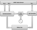
sensor.jpg

the simplest thing i know is that an antenna is connected to transmitter side, transmits signals and a receiving antenna receive the signal... what is the need of a delay line in this structure. is it used for extracting phase information of the complex signal or what else it gives
 

hi,this is fani from india
radars for detecting moving targets only employs delay lines, b'coz the radar should cancel the information receving from clutters(stationary targets)
this can be done in two ways
1)butterfly method
2)delay line cancellors
1st method is not suitable for ppi scopes so we use delay line cancellation
---> the simple working of a delayline based radar is the data from receiver is delayed for one time period and applied to a subtractor circuit to which the other input is actual data with no delay.
---.since the clutter information is constant eventhough it is delayed so it cancels out,so RADAR only detects moving targets


Sorry for the lengthy answer,if u have any doubts in this u can post me:lol:
 

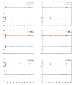
thanks fani for your response. I wont go into such complex explaination of this. actually i have to extract some information from such setup that we used in out university lab. i can provide the recored data ploted as inphase and quadrature values...
2556782.gif
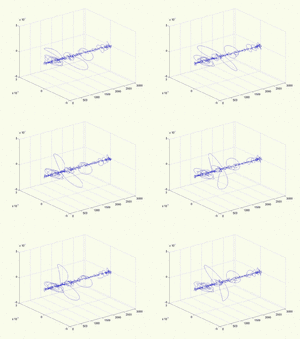
its a gif file combination of 100 data samples at 100 delay points. if we plot both inphase and quadrature data in 3d i get such thing
interpolated.gif

actually i am confused because we studied that due to delay line the signal changes it's position along with rotation in polar form. but here i see only rotation and no position change.

apart from it. what information can we extract from these two graphs, about received signal....
 

Status
Not open for further replies.

Part and Inventory Search

Welcome to EDABoard.com

Sponsor

Back
Top