Continue to Site

Welcome to EDAboard.com

Welcome to our site! EDAboard.com is an international Electronics Discussion Forum focused on EDA software, circuits, schematics, books, theory, papers, asic, pld, 8051, DSP, Network, RF, Analog Design, PCB, Service Manuals... and a whole lot more! To participate you need to register. Registration is free. Click here to register now.

[SOLVED] SPI termination resistor

Status
Not open for further replies.

rayhh27

Member level 1
Joined
Nov 22, 2016
Messages
34
Helped
0
Reputation
0
Reaction score
0
Trophy points
6
Activity points
361
Hi,

I have some question regarding SPI PCB routing.
1. For a short trace such as 30mm, do we actually need a termination resistor to damp the reflection?
2. Does a 0.18mm width of trace enough to give clean signal for SPI clock?
3. Is it true that it is not recommended to use via for clock signal in general?
4. From my research over the internet, I found that MISO pin on SPI need a pull down resistor like around 100k, is this actually necessary?
5. For the value of termination resistor, I read that it is the value of the trace impedance and the driver impedance, lets say that the trace is 50 ohm and the driver impedance is 20 ohm, so I will need a termination resistor of 70 ohm? Is this calculation correct?
6. Thank you very much.

Best regards,

RH
 

Hi,

first: what SPI clock frequency do you expect?
Your posts seem you want to transmit with more than 100MHz clock speed. Not typical.
I ask myself: How do you come to such extreme assumtions? Where did you read about this? Give a link.
In my eyes you over complicate things.

1) i never heard that standard SPI needs termination at all.
2) it´s not critical.
3) Not true. Where did you read this?
4) Again: give your source of information. Never heard about it.
5) termination works differently. You don´t need to care about this here.
But where termination is needed: Driver impedance, trace chracteristic impedance and termination resistance should have the same value.

Klaus
 
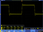
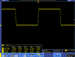
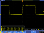
Sometimes when going short distances with such clocks the energy put onto the line is excessive causing reflection, these are best solve using a series resistor to limit the energy being put into the line. The driver may need to drive a long trace so they go for a highish drive strength to make sure there is the power to drive the line. The attached picture illustrate this and how different values of resistors tame the ringing. You can also achieve a similar result with ac AC parallel termination (resistor and cap pull down or up) but for limiting the energy the series terminator as close to the source is best.
The best place to investigate this sort of thing is using SIV (signal integrity verify) tools where you can look at the graphs of driver outputs from the IBIS data.
 

Attachments

  • 16MHz.png
    16MHz.png
    66.2 KB · Views: 490
  • 22R_Term_AP.png
    22R_Term_AP.png
    41.6 KB · Views: 365
  • 68R_Term_AP.png
    68R_Term_AP.png
    39.3 KB · Views: 445
  • 82R_Term_AP.png
    82R_Term_AP.png
    36.5 KB · Views: 394
Hi,

I am just expecting 5.5MHz clock. I know I seem to overcomplicate things here, however this is because I really does not have any experience in using SPI.
I believe it is better to overcomplicate things and ask rather than be ignorant and fail. However, I am really thankful for your answer.

Here is some fact about my project
1. The SPI BUS is for communication between MAX 10 and GPS LEA-M8T, I believe this is just a normal SPI protocol. In spite of that, I want to know better whether there is any constraint in connecting the BUS.
2. Most of the information I get is from another forum, mostly stackexchange. I state it here because I believe that I do not know anything and I want to clarify some of the facts.
3. Hearing that you believe that it is not actually so complicated, it really ease my mind. Thank you.

Best regards,

Raymond
 

The usual termination scheme for single ended TTL/CMOS signals is source side series termination. In your example, you would add a series resistor of 30 ohms to achieve matching to the 50 ohms line. (More likely, the line impedance is something like 70 ohms). Termination is meaningful for high speed clocks >= 50 MHz and long SPI busses, so probably not necessary in your design.

MISO pull-up or -down resistors might be used to avoid floating of the signal to mid-level with increased current consumption of the receiver buffer. That's particularly interesting in a low power system with only occasional activation of the SPI bus, but not necessary in a typical processor system.
 
I find your answer very clear and easily understandable. Thanks a lot.

Best regards,

Raymond
 

you do not need a series termination resistor on the SPI lines unless the length of the line is very long and the clock rate very high. A pull up resistor maybe needed on the MISO on things like SD cards as it will stop the line floating and can also be used as a way to detect if the SD card is inserted.
 
Status
Not open for further replies.

Part and Inventory Search

Welcome to EDABoard.com

Sponsor

Back
Top