Pancra85
Junior Member level 1
Thank you very much for taking the time to read this and help me!
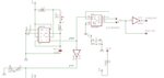
I designed this circuit which I think is a pulse generator, made with a 555 IC, counter and an inverter to generate a ryhtm for the drum machine:
Out of the picture (down) is a hi-hat circuit.
First of all this part is working fine, it generates a desired pulse and is having no problems by itself, also the hi-hat works fine in rhythm.
I also made two PCBs for this circuit: **broken link removed** and connected each one (bass and snare) to the designed pins on the right of the first image. That also works fine by itself.
As I also want the drum and snare to be triggered by a button when the snare and bass ryhtm is disabled (by disconnecting the switch on the right of the first image, next to the snare and bass rhythm output pins) so I also connected a button to +9v and the other pin of the button to each trigger and THATS WHERE THE PROBLEM IS.
When I press the bass button it first triggers a bass drum sound, but when I realease it it makes a snare drum sound, also it seems that the snare button doesn't triggers the snare at all.
I tried putting a very small resistor (10 ohms or 220 ohms) from bass trigger to GND but it makes the same thing.
Help pleaseeeee??? Thanks!!!