Continue to Site

Welcome to EDAboard.com

Welcome to our site! EDAboard.com is an international Electronics Discussion Forum focused on EDA software, circuits, schematics, books, theory, papers, asic, pld, 8051, DSP, Network, RF, Analog Design, PCB, Service Manuals... and a whole lot more! To participate you need to register. Registration is free. Click here to register now.

Regenerative receiver with zero tap coil?

Status
Not open for further replies.
This is not a regenerative receiver. It is a Direct Conversion, using separate Colpitts oscillator, and a FET is used as a (Gate) Additive Mixer.
 

Hello I have found this circuit
https://www.qsl.net/7n3wvm/regen.html

1. Is it really a regenerative circuit?
Yes.

2. How is feedback to the fet applied, since there is no tap on the coil?
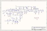
The Q-multiplication (i.e. feedback or regeneration) takes place in the 2SC1815 bipolar junction transistor at the top-left of the diagram. That transistor is configured as a common-collector (voltage follower) Colpitts oscillator that is lightly coupled to the LC resonator (tank) through a 33pF capacitor connected to the base. The tank signal enters the transistor at the base, and an amplified, non-inverted, in-phase signal appears at the emitter across the 3.3k emitter resistance. That amplified in-phase signal is fed into the 100pF/100pF capacitive divider, where it is coupled through the 33pF capacitor back into the LC resonator for regenerative feedback.

The 10k-ohm variable resistor at the base is a voltage divider that varies the base bias to control the amplifier gain and thus the amount of feedback (regeneration). The BJT, not the FET, is therefore doing the regeneration in this circuit. For AM reception, the feedback is adjusted just below the oscillation threshold. For CW or SSB reception, it is adjusted just above oscillation.

The JFET, biased near pinch-off for nonlinear response, serves as a square law detector to change the modulated and Q-multipled RF signal (available at the tank) back into AF. Its high input impedance allows it to be connected directly to the tank.

There are other regenerative receiver topologies that do not require tapped coils or a separate feedback coil. A cross-coupled oscillator and a negative resistance oscillator are two examples.
 

You can try to build the kit that is available at website:
**broken link removed**

It is a radio receiver regenerative type of high performance.
All the best, Neculai

- - - Updated - - -

You can try to build the kit that is available at website:
http://scitec.hubpages.com/hub/High-Performance-Regen-Receiver

It is a radio receiver regenerative type of high performance.
All the best, Neculai
 

....and this is the schematics! :roll:

Regen V1.0.0.jpg
 

Status
Not open for further replies.

Part and Inventory Search

Welcome to EDABoard.com

Sponsor

Back
Top