Continue to Site

Welcome to EDAboard.com

Welcome to our site! EDAboard.com is an international Electronics Discussion Forum focused on EDA software, circuits, schematics, books, theory, papers, asic, pld, 8051, DSP, Network, RF, Analog Design, PCB, Service Manuals... and a whole lot more! To participate you need to register. Registration is free. Click here to register now.

RDVV 5 WATTS MOUTOULOS

Status
Not open for further replies.

Imalu3055

Member level 1
Joined
Dec 23, 2020
Messages
36
Helped
0
Reputation
0
Reaction score
0
Trophy points
6
Activity points
273
Hello!

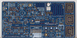
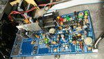
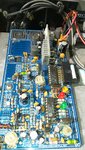
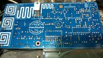
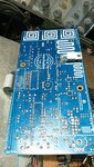
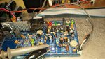
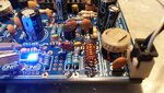
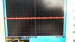
I have bought RDVV 5w Moutoulos PCB - GP Electronics (from Greece) on eBay. I used the components exactly indicated and checked before soldering. When I connected the 12 volts the PIC worked correctly but THE OSCILLATOR DID NOT WORK!

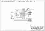
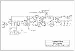
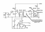
I checked again and noticed no errors. I replaced the varicaps with a 22pF capacitor and the oscillator did not start. I replaced the coil L of the Colpits oscillator with others recommended by the author, who does not respond any more, the original is: 8 turns of copper of 0.5mm and 3mm internal diameter (not working), 9 turns of copper of 0.5mm and 3mm inner diameter and 4 turns of 1mm and 6mm inner diameter copper and it didn't work. I replaced the 680 ohm resistor from JFET J310 (they recommend replacing the BF245 with J310) source to GND with a 47uH choke, it didn't work either. I replaced the JFET and it didn't work either.


After several attempts to communicate with the author of the printed plate, who manufactures and sells FM transmitters, he responded evasively and did not provide any information. I appeal to the knowledge of the members of this forum.
Thanks a lot.


Ícono de validado por la comunidad
Claudio Denegri
 

Attachments

  • Impreso Lado Componentes.jpg
    Impreso Lado Componentes.jpg
    1 MB · Views: 205
  • rdvv-2006v6-pic16fxxx-schematic.jpg
    rdvv-2006v6-pic16fxxx-schematic.jpg
    121.7 KB · Views: 164
  • rdvv-notune-2006v6-8watt-schematic.jpg
    rdvv-notune-2006v6-8watt-schematic.jpg
    80 KB · Views: 204
  • rdvv-notune-2006v6-pll-tsa5511-schematic.gif
    rdvv-notune-2006v6-pll-tsa5511-schematic.gif
    35.6 KB · Views: 254

Hi,

show photos of the PCB with parts soldered on it. Top and bottom side.

Klaus
 

Hi Klaus,
 

Attachments

  • 20210328_135649.jpg
    20210328_135649.jpg
    2.8 MB · Views: 129
  • 20210328_135707.jpg
    20210328_135707.jpg
    1.3 MB · Views: 183
  • 20210328_135807.jpg
    20210328_135807.jpg
    2.6 MB · Views: 108
  • 20210328_135901.jpg
    20210328_135901.jpg
    1.1 MB · Views: 104

Hi,

Are you sure the diodes really are 1N4148 and orientation is correct. I'm not sure.
I've never seen 1N4148 with those colors.

Klaus
 

It's well over 30 years since I've used a 1N4148 in a glass package, but I used so many I doubt if I'll ever be able forget the colours, they look OK to me.
 

Hello!

If you look correctly you will see that none of the 1N4148 affects the oscillator, with which I have problems ... and yes, they are 1N4148 and they are correct.
Any help with the oscillator?

Thank you
 

HI,
If you look correctly you will see that none of the 1N4148 affects the oscillator, with which I have problems ... and yes, they are 1N4148 and they are correct.
Any help with the oscillator?
Help me to look correctly.
Does one of the schematics clearly show which parts belong to the oscillator? With or without PLL? With or without the according power supply? With or without the according regulation voltage? With or without the load circuit?

I see a white box painted on the PCB named "oscillator" ... within the box there are 1N4148.
But I have to admit I did not cross check with the schematic.
In the past I worked with 1N4148 with brownish color and one single yellow band. I asked to check.

You said you already checked everything. Everything is correct. But still it does not work.
If we focus just on the 10 parts of the colpitts oscillator we focus on the parts that that you already have checked.
We are limited.
Imho we need to widen the view.

You are the boss. So it's O.K. if you tell the rules.

Klaus
 

Often it helps to vary supply voltage to an oscillator. There may be a certain range of operation such that transistor bias is the right amount, and sufficient swing, in order to draw necessary power from the supply, and feed it to the LC network, in order to maintain resonating oscillations.
 
Hello
BradtheRad

Exactly!!! He didn't remember that quality of oscillators. Tomorrow early I will experiment on it.
Thanks a lot
--- Updated ---

Hi
KlausST

Thanks for your answer.
I don't consider myself a boss, quite the contrary.
The 1N4148 diodes are part of the bias of the transistors that operate in class c.
BradtheRad I think "hit the spot"
Tomorrow I will comment on my experiences. Thank you all for the incredible good predisposition. Thank you very much.

This forum site is amazing, the best


Ícono de validado por la comunidad
 
Last edited:

Hello!

I comment that I have found that the JFET J310 cerigraphy is printed in reverse and therefore I have mounted the transistor backwards. I replaced the transistor with a new one but the circuit remains "dead", it does not oscillate.
I tried to vary the supply voltage but no oscillations. It really strikes me that this vendor is the only one that uses a JFET as an oscillator, the rest use a double gate MOSFET, the BF980.
Well ... As we say in my country: "My papers have been burned ..."

If someone is an expert in "COLPITTS", welcome their knowledge.
Thanks a lot.

Ícono de validado por la comunidad
 

I've used that oscillator configuration lots of times and never had a problem.

The oscillator transistor says BF245C but the one fitted is an MF245, I'm not sure if that makes any difference. The pins on a BF245C, looking at the flat side with pins facing down are G-S-D but the PCB is marked D-S-G which is correct for the BF244 but not the BF245. You may have the gate and drain swapped over and that would certainly stop it running!

Brian.
 

Hello Brian!!

How nice of you to provide this information. When you refer to the MF245 ... on which plate or mount did you observe it? In the FM Transmitter that I am trying to operate I did not see it.
I have been recommended to replace the BF245C with the J310 as it would get better results. Tomorrow I will experiment with the "L" coil, as the seller does not provide concrete information. On the one hand it says: 8 or 9 turns of Cu 0.5mm in 3mm diameter, then 10 turns of 4mm diameter and 4 turns of Cu 1mm in 6mm diameter. As long as the final inductance remains at the right value it could be any ... Anyway, I'll see.

Thanks
 

How do you know that the oscillator does not work ?? Do you have a Spectrum Analyzer ??
Because of some other issues, PLL might not lock ? Have you ever checked Voltages and Currents of the circuit parts ??
 

Hi BigBoss !!!

I have a 200MHz bandwidth oscilloscope.
 

Hi,

Tell us more: what are the DC voltages at the oscillator nodes?
Especially all 3 voltages of the transistor w.r.t. GND.

Klaus
 

Looks like MF245C in the first picture of post #3 but maybe just the way the camera sees it.
Regardless, the PCB legend doesn't match the pins on a BF245C and if fitted the wrong way around it certainly will not work.

Forget the PLL for now, the oscillator should still run if you remove it entirely and it won't even be far off frequency. If monitoring using your 'scope, do not connect directly to the coil, either probe at the source pin of the FET or better still, at the collector of the BFR96. I doubt very much whether a J310 would make any difference to performance, it is only an oscillator stage.

Brian.
 
Before looking for oscillator output, I would check the DC voltages, it will reliably tell if the JFET has been assembled with correct pin order and is working in a bias point suitable for oscillation.

I would also check varicap polarity.

The PCB silkscreen fits J310 pin order, but not BF245, as already stated, and neither BF244. I would expect, that the oscillator works with 180° rotated BF245C as well.
 
Last edited:

Hello!

I have measured voltages on pins of the JFET and GND. They seem illogical to me. You can see them in the attachment. I built a new "L" coil as recommended by the PCB designer. I observed a lot of noise in the power supply, I do not think this affects the operation of the oscillator, but I will fix it. The frustration that a hundred at age 63 after having assembled much more elaborate circuits is very great, as well as regretting that the seller does not provide concrete and precise information.

Thanks a lot
 

Attachments

  • 20210330_114921.jpg
    20210330_114921.jpg
    837.7 KB · Views: 111
  • 20210330_115036.jpg
    20210330_115036.jpg
    418.9 KB · Views: 80
  • 20210330_115106.jpg
    20210330_115106.jpg
    243.5 KB · Views: 76
  • Medicion copy.jpg
    Medicion copy.jpg
    56.8 KB · Views: 136

From those voltages I would deduce the FET is the wrong way around! Expect something close to zero, maybe even a little negative on the gate and more difference between the source and drain pins.

I can see you have reversed it but that isn't the problem, they are still wrong. Check the pin names from the FET data sheet then wire them to the PCB accordingly. Don't assume the outline on the board is correct.

It will oscillate with almost any size of coil although not at the right frequency so I wouldn't worry about that too much, get it oscillating first then fix the frequency later. I wouldn't think the PSU has anything to do with this problem, the most it would do is cause noise on the transmission and in any case, there is a voltage regulator on the board that should trap most of the main PSU interference.

Brian.
 
Hi,

The schematic shows 6.35V at the gate.
I wonder how this can be.
The only DC path is via the 47k resistor. And it pulls to GND. So I´d expect 0V here.

For proper operation I expect a second "biasing" resistor to VCC (or somewhere else).

Klaus
 

Status
Not open for further replies.

Part and Inventory Search

Welcome to EDABoard.com

Sponsor

Back
Top