Continue to Site

Welcome to EDAboard.com

Welcome to our site! EDAboard.com is an international Electronics Discussion Forum focused on EDA software, circuits, schematics, books, theory, papers, asic, pld, 8051, DSP, Network, RF, Analog Design, PCB, Service Manuals... and a whole lot more! To participate you need to register. Registration is free. Click here to register now.

need some help creating a circuit

Status
Not open for further replies.

FSR

Newbie level 1
Joined
Feb 20, 2012
Messages
1
Helped
0
Reputation
0
Reaction score
0
Trophy points
1,281
Activity points
1,302
Hi there, my name is Neil, and i have a question for all willing to help

FSR stands for "Focus sport rally" I am currently in the process of building up a 2002 ford focus zx3 into a rally car.
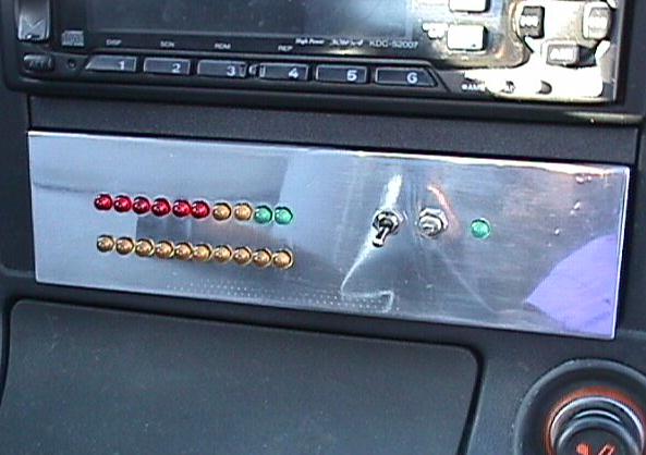
what I'm looking to do, is build a circuit which will allow me to have three rows of ten LEDs to sequentially light up with the movement of the clutch,brake, and the accelerator
such as...

6906476345_d3072b0bc8_z.jpg


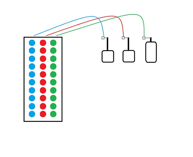
I would like it so that if the accelerator is full throttle all ten green LEDS will be lit, if its half only five will be lit and so on.. that would be the same for the clutch and brake now i have done some circuitry in school as well as just some hobby stuff, but I feel I'm either over thinking this or I am out of my league.

I have toyed with using servos to move a conductor over open contacts connected to the leds, however i feel this would not be responsive enough for my overall objective.
any help would be greatly appreciated
thanks
Neil
 

I'd start with something like an LED bar driver chip for each of your three channels (clutch, brake, throttle). Read the spec sheet for this part and see if it fits your needs. **broken link removed**

If this part works, you'll need to determine a way to get an analog voltage that follows your pedal positions. Have you done any thinking about how you'll accomplish that?
 

I agree with enjunear although there are other alternative parts. I'm not sure the LM3914, 3915 and 3916 are available these days although they would be the ideal part to use. By far the biggest problem is extracting a voltage from the movement of the pedals. There is probably a voltage available somewhere that relates to the accelerator as the car has electronic control but I would be very hesitant to suggest you connect directly to it in case you inadvertently upset normal operation. Mounting potentiometers near the pedals isn't a good idea either, being kicked won't do them much good and if they obstruct foot or pedal movement it could lose you the rally or worse. Take a good look at ways you can convert pedal movement into shaft rotation, ideally through more than 180 degrees as the pedal traverses it's range. The electronic part of the problem is easy.

Brian.

Along Brian's way of thinking, you might explore linear potentiometers. Rather than converting linear pedal travel into rotation (to turn a normal pot), you can connect them directly (much thought and tweaking is often needed to get them fixture'd up correctly, so they won't bind up). The items I found several years ago were somewhat expensive, but did the job (solar-powered vehicle w/ drive-by-wire throttle). You might do some web searches for "linear potentiometer" and similar words to see what's out there. Check places like digikey, newark, etc for pricing.
 

Maybe to use hall sensor in upper part of pedals at reed sensors place, to sense magnet distance (field strength) :
**broken link removed**

When you make that see this for next step :
**broken link removed**
9.jpg
 

1.

For the accelerator, also consider a photosensor detector. Mount an led on the gas pedal. (Keep the wires clear of your feet.)

Then place the sensor to detect either led brightness, or led position. Getting consistent readings will not necessarily be easier than the potentiometer method.

Then there is the problem of unpredictable light levels where the pedals are.

2.

Brake pressure will not be easy to detect. The pedal moves in a small range between low pressure and high pressure.

It might work to put a pressure sensor on top of the pedal, to detect how hard your foot is pressing. However your foot must always make uniform contact with the pressure sensor each time, which cannot be guaranteed.

As mentioned already, it's vital not to attach your device so it interferes with brake operation.

3.

As to the clutch, do you want to detect clutch slippage? The straightforward way is to detect shaft rpm before the clutch, and compare it to shaft rpm after it. This may be possible to do electronically.

Or it may be easier to detect pedal position. However you must position your sensor at just the point where you notice clutch action taking place. And you must detect the range of pedal motion (say 1/4 to 1 inch), and turn it into a variable voltage. This might be by light sensing, since a 1/8 inch wide sensor could be illuminated by an led attached to the pedal, and pick up the range of pedal movement.
 

I agree with BradtheRad. But all of this must be done very carefuly I think will be very bad that something stuck between pedals at 160km/h. :-| I think tha law regulations also prohibit any changes on car control parts....

I would like to be in that car when pedals stuck. :-D

It will be like in movie Speed '94 with Sandra Bullock.
 
Last edited:


why you not use direct interfacing of any microcontroller with your car speedometer and RPM meter...
OR use liner variable resistor at clutch,brake,accelerator wire..
 

why you not use direct interfacing of any microcontroller with your car speedometer and RPM meter...
OR use liner variable resistor at clutch,brake,accelerator wire..

Please can you give us one example how to fix variable resistor on pedal shaft ?
 

liner variable resistor's throttle connected to clutch,.., wire and variable resistor at any nearly object.
By using microcontroller insted of ICs you can also view status at display and controll other things.
 

You have to make/buy three LVDTs. Hang them from somewhere top of pedal arms. Connect the other end of the LVDTs to the pedal arms. Do not make drill in the pedal arms. Then make necessary electronics using LM3914/3915/3916. You have to think mechanical to install the LVDTs. You have to consult with mechanical engineer/technician to install the LVDTs. They know various types of clamping technique.
 

Status
Not open for further replies.

Part and Inventory Search

Welcome to EDABoard.com

Sponsor

Back
Top