Continue to Site

Welcome to EDAboard.com

Welcome to our site! EDAboard.com is an international Electronics Discussion Forum focused on EDA software, circuits, schematics, books, theory, papers, asic, pld, 8051, DSP, Network, RF, Analog Design, PCB, Service Manuals... and a whole lot more! To participate you need to register. Registration is free. Click here to register now.

Need help with my IoT Project ESP8266 NodeMcu to ESP12-E

Status
Not open for further replies.

Osfuco

Newbie level 5
Joined
Mar 27, 2021
Messages
8
Helped
0
Reputation
0
Reaction score
0
Trophy points
1
Activity points
69
Good evening, I am doing a project in which I want to measure air quality. I started the project with the ESP8266 NodeMcu board and three sensors, temperature (DHT22), VOC's (CCS811) and PM (PPD42).

I have it all assembled with a breadboard and the NodeMcu and it works fine.

The fact is that I want to pass it to PCB and I am a little lost. From what I've been reading, I have to use the same board but without NodeMcu, so I use ESP12-E.

I have tried to make a design on the web https://easyeda.com/, (I attach images). I copied the connections that I already have working and grouped all the GND connections in a single point.
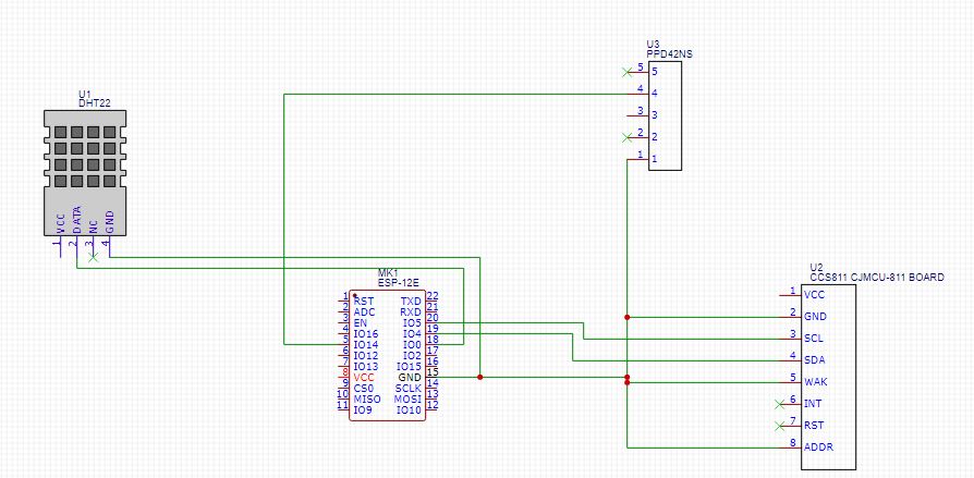
Image


The 3V3 pins I still have no idea how to do it, if anyone can give me a hand I would appreciate it.

Am I wrong or am I on the right track?

Thanks a lot! :):
 

On the right track but not quite at the destination.

Firstly, the nodeMCU has an on-board 3.3V regulator so you may need one to feed the ESP's VCC pin. If you do, note that despite their small size, that can draw over 0.25A peaks during WiFi operation so you also need capacitors from VCC to GND.

Secondly, the ESP-12E has several boot modes which have to be set before the power is applied. Off hand I can't remember which pins have to be at high level or low level but an internet search should tell you. So you probably need resistors from some pins to GND and other pins to VDD, they are already fitted on the nodeMCU but you must add them to a naked ESP-12E.

I am just about to do this myself after prototyping a PV powered WiFi thermometer. The nodeMCU draws 8mA (mostly through the USB interface and power LED) even while the ESP is in reset so I have to dispense with all but the ESP to reduce drain on the battery or it empties overnight!

Brian.
 

I have to use the same board but without NodeMcu, so I use ESP12-E
A long time ago I tried to migrate a project based on the NodeMCU ESP32-based board to the ESP32 single module and I sketched what should be added to the "main board" where the module should be soldered, as seen bellow ( left side ). In other words, I splitted the original NodeMCU board into two circuits, one having the whole content of the single module ( right side ), and another one containing the remaining circuits:

I think you should do the same for your case, with the ESP9266.

Gravador_com_placa.png
 

On the right track but not quite at the destination.

Firstly, the nodeMCU has an on-board 3.3V regulator so you may need one to feed the ESP's VCC pin. If you do, note that despite their small size, that can draw over 0.25A peaks during WiFi operation so you also need capacitors from VCC to GND.

Secondly, the ESP-12E has several boot modes which have to be set before the power is applied. Off hand I can't remember which pins have to be at high level or low level but an internet search should tell you. So you probably need resistors from some pins to GND and other pins to VDD, they are already fitted on the nodeMCU but you must add them to a naked ESP-12E.

I am just about to do this myself after prototyping a PV powered WiFi thermometer. The nodeMCU draws 8mA (mostly through the USB interface and power LED) even while the ESP is in reset so I have to dispense with all but the ESP to reduce drain on the battery or it empties overnight!

Brian.
Hi, I have already configured the 5V input with micro USB and regulator to 3.3V.

Now I don't know what high level or low level means. On which pins and how do I put the resistors in the GPIOs that I use in sensors?

Thank you very much, I leave the link so you can check it
 

At power up the ESP8266 needs to know whether you want to run the code inside it or program new code into it. It does that by looking at the logic levels on three of the pins. For normal operation GPIO0 and GPIO2 must both have a logic high on them so both need resistors (~10K) to the VDD pin. GPIO15 has to be at logic low level so for that pin wire a resistor (~10K) to VSS. After starting up you can still drive those pins or use them as outputs as you wish, it is only as it starts up the levels have to be set.

You should really also add another resistor (~10K) between RST and VDD, this will ensure the device isn't stuck in reset mode. You can pull the pin to VSS if you need to reset it externally.

You almost certainly need yet another resistor (~10K) between 'EN' and VDD to ensure the device doesn't go into standby state.

Brian.

Hello good,

First of all, thank you very much for your help.

I have updated the scheme with all the resistors, regulator and USB, I leave you the link to see if you can confirm that everything is correct.

I wanted to ask you some questions:
What is the "1N5819" (VVDDUSB - 1N5819 - VDD5V) for?
Now if I print this scheme, should everything work correctly?
Is there a way to simulate it before printing?
How to program without the NodeMcu?

Thank you so much for everything

Oscar
 

The 1N5819 is a Schottky diode, one that can carry quite a lot of current but also has a low voltage drop. It allows current to flow from the USB socket (5V) to power the board but blocks any voltage you apply to the 5V nodeMCU pin from flowing back to the USB socket. Without it, if you powered the nodeMCU from an external supply it could damage the host USB interface or even try to power other USB devices plugged in to it.

There is currently little you can do to simulate it before programming the module I'm afraid. Even the new Arduino 2.0 system doesn't seem to support ESP debugging. I believe it may be possible using some other IDE but i haven't tried it.

You need a serial interface to program the ESP module. With the correct pin levels when you power up, it goes into programming mode and accepts formatted code through the TX and RX pins. I use one of these for speed:
but they are available from several sources. The module sits inside spring clips for programming and code development but can be flipped out and soldered directly to a final board afterwards. Beware that I have several of these and ones for ESP32 and some of them have manufacturing errors so give them a good looking over before powering up. Several have the power switch rotated 90 degrees so it doesn't work and some have the power LED fitted backwards.

The resistors on the schematic should be fine to make it run.

Brian.
 

Status
Not open for further replies.

Part and Inventory Search

Welcome to EDABoard.com

Sponsor

Back
Top