Welcome to our site! EDAboard.com is an international Electronics Discussion Forum focused on EDA software, circuits, schematics, books, theory, papers, asic, pld, 8051, DSP, Network, RF, Analog Design, PCB, Service Manuals... and a whole lot more! To participate you need to register. Registration is free. Click here to register now.
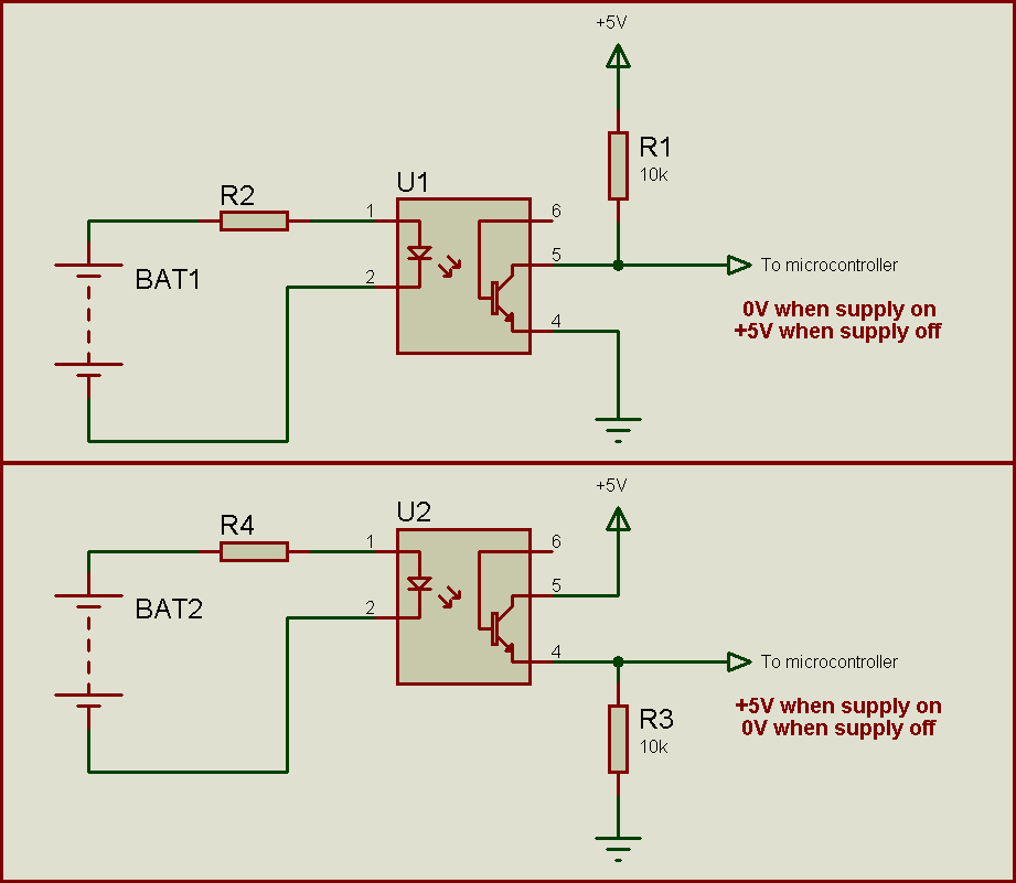
Use the supply to drive the opto-isolator LED. If the supply is AC, make sure you rectify it to DC. Remember to use a current-limiting resistor.
At the transistor side, connect the emitter to ground. Connect a resistor (10k) between the collector and +5V. Connect the collector to the microcontroller. In this configuration, when supply is on, the output at the collector and thus to the microcontroller will be 0. When supply is off, the output at the collector and thus to the microcontroller will be +5V.
Another possible configuration is to connect the collector to +5V and to connect a resistor (10k) between the emitter and ground. Connect the emitter to the microcontroller. In this configuration, when supply is on, the output at the emitter and thus to the microcontroller will be +5V. When supply is off, the output at the emitter and thus to the microcontroller will be 0.
Here I've used +5V for the examples. If your microcontroller is to be operated with 3.3V, then use +3.3V instead of +5V.
This site uses cookies to help personalise content, tailor your experience and to keep you logged in if you register.
By continuing to use this site, you are consenting to our use of cookies.