Continue to Site

Welcome to EDAboard.com

Welcome to our site! EDAboard.com is an international Electronics Discussion Forum focused on EDA software, circuits, schematics, books, theory, papers, asic, pld, 8051, DSP, Network, RF, Analog Design, PCB, Service Manuals... and a whole lot more! To participate you need to register. Registration is free. Click here to register now.

Measuring the Radiation Fields of a Parabolic Reflector

Status
Not open for further replies.

denizduran

Member level 2
Joined
Sep 14, 2021
Messages
48
Helped
0
Reputation
0
Reaction score
1
Trophy points
8
Activity points
463
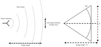
There is a 24.25 GHz Reflector design that needs to be tested. When calculating the radiation zones of the reflector, do we calculate far-field = 4 * Raleigh zone? And if so, why is the calculation in terms of the Raleigh zone and there is no mention of the Fresnel and Fraunhofer regions?
 

Yes I see. When I calculate the zones for my reflector, they turn out as follows:
- Rayleigh Region: 2.49 m
- Fresnel Region: 55.26 m

So to detect far-field patterns, the reflector must be placed at least 55.36 m away. But according to this link: https://en.wikipedia.org/wiki/Reflector_(antenna) it says that "A distance of four Rayleigh distances is commonly adopted as the minimum distance at which measurements can be made". And 4 x 2.49 = 9.96 m which sounds like a more reasonable distance. What do you think?
--- Updated ---

The distance limits of the radiation zones (Fresnel, Rayleigh, Fraunhofer) of a dish reflector, happen at the same distances as for any other antenna type.
The Rayleigh distance is the demarcation boundary between the near-field Fresnel zone and the far-field Fraunhofer zone.

Also, safety is not a concern since in our case in far-field, our power density is 7.007 x 10^-4 W/m^2 and even when its placed at 9.96 m (4*Rayleigh distance) our power density is 0.022 W/m^2 which are all way below 10 W/m^2. I just want to know what distance I need to place my dish to measure the far-field radiation pattern.
 
Last edited:

The far-field concept is related to ensure an almost plane wave is illuminating the antenna under test by the source antenna.
For better understanding, in the picture attached, ΔФ = (ΠD^2)/(4λR)
If the ΔФ = Π/8 or 22.5° then we get the well-known far-field distance R = (2D^2)/λ.
The 22.5° is the acceptable allowable phase variation to give the required accuracy in measuring the antenna under test gain and pattern.

However, for the parabolic reflector antenna case due to its construction, the waves leaving the antenna are almost parallel one to each other, giving a nearly plane wave front.

So in this situation, this might be the reason that some people may chose smaller distance for far-field, other than (2D^2)/λ.
 

Attachments

  • phi.jpg
    phi.jpg
    54.6 KB · Views: 106
Status
Not open for further replies.

Part and Inventory Search

Welcome to EDABoard.com

Sponsor

Back
Top