Continue to Site

Welcome to EDAboard.com

Welcome to our site! EDAboard.com is an international Electronics Discussion Forum focused on EDA software, circuits, schematics, books, theory, papers, asic, pld, 8051, DSP, Network, RF, Analog Design, PCB, Service Manuals... and a whole lot more! To participate you need to register. Registration is free. Click here to register now.

logic of mode excitation using pin fed inside horn antenna

Status
Not open for further replies.

yefj

Advanced Member level 4
Joined
Sep 12, 2019
Messages
1,199
Helped
1
Reputation
2
Reaction score
3
Trophy points
38
Activity points
7,238
Hello,In order for the horn antenna to operate we need to generate in the waveguide a TE10 mode.
this mode have a cuttof wave length of a*2 where "a" is the width of the waveguide.
So i assue that the "a" of the wave guide needs to be linked somehw to the length of the monopole.
How exactly we know what monople length to put so we will get halfwavlength electric field pattern accross the "a" (width of the waveguide)
the monopole pin is much smaller then the width of the waveguide.
How exactly one antenna (much smaller in length) can excite a TE10 MODE where the width of the waveguide is much larger?
obviosly they dont have the same halfwavelength dimention.
Thanks.

1624687481229.png
 

The length of the monopole probe should be λ/4, or 3λ/4,...
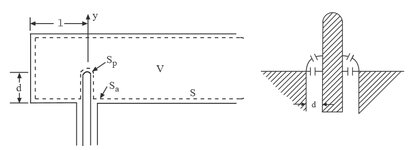
By proper adjustment of the distance d and length l (left picture attached) can cause almost all the power from the coaxial line to be transferred to the waveguide, with minimum reflections. For maximum transfer of the power, the probe input impedance should be matched to the characteristic impedance of the transmission line.
Gap capacitance (right picture) should be taken into consideration to find the input impedance of the probe. An EM simulation can help designing the waveguide probe.
 

Attachments

  • probe.jpg
    probe.jpg
    50.4 KB · Views: 137

Hello Vfone,the monopole pin is smaller then the width of the waveguide.
How exactly one antenna (much smaller in length) can excite a TE10 MODE where the width of the waveguide is much larger?
obviosly they dont have the same halfwavelength dimention.
Thanks.


a probe is positioned in the centerline of the waveguide. therefore it is trying to excite the waveguide at the "easiest" point, where the RF voltage (or Efield) is a maximum. IF you position your probe from the shorting plate at the rear of the waveguide, that makes it even easier to excite the Efield, because that is a point where the standing wave voltage is 2 X higher (roughly the pin placed at a quarter wave from that shorting plate)

but you are not necessarily trying to make the pin probe length to be quarter wave long. As you are injecting a signal into the waveguide, mostly capacitively, into that waveguide, you can vary the length and diameter of the exposed portion of the pin so that the impedance looking into the external coaxial connector is 50 ohms.

you can play around with pin length, diameter, shorting plate location, other items, to try to get a much wider bandwidth

Hewlett packard came up with a full waveguide band transition design that used multiple quarter wave waveguide steps to a pin that was shorted to the WG at its end, P281C is one part number. if i recall, there is a paper somewhere (maybe the IEEE) describing the design

i have had some good luck with a crossbar across the waveguide width, with the coax pin soldered to the middle of the crossbar. it is a magnetic coupling, that for some reason has a bigger bandwidth than an Efield probe.
--- Updated ---

some good drawings here:

 
Last edited:

Status
Not open for further replies.

Part and Inventory Search

Welcome to EDABoard.com

Sponsor

Back
Top