Welcome to our site! EDAboard.com is an international Electronics Discussion Forum focused on EDA software, circuits, schematics, books, theory, papers, asic, pld, 8051, DSP, Network, RF, Analog Design, PCB, Service Manuals... and a whole lot more! To participate you need to register. Registration is free. Click here to register now.
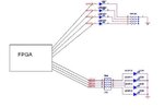
well on the top is using a 10k and on the bottom there is a 330 ohm closer to the fpga!
if you want to know which is better, all things being equal I would probably put the resistors closer to the fpga. The bottom one will be easier to remote one of the leds. depends on your board layout.
ya off-course,
But if layout is not an issue then the below one will be more bright. One more thing this 10K and 330E depends for what I/O voltage you are biasing the LEDs
So I will say that the data provided by you is insufficient. If will assume I/O voltage as 3.3V which is max in current FPGAs then 330E LED connection is correct,giving 10mA of current.
In case of 10K current is only 0.33mA which is I think not sufficient to drive your LEDs.
Hi ,
why i ask this question is in our FPGA we have 8 leds connected as the top schematics with 10k restister.At the time of power ON all led glowing. I don't no why this leds are glowing.but it should be in off state .
I think the leds are on because all I/O pins have an internal pull up resistor while the chip is in program mode or when it is not programmed.
Open the datasheet of your fpga and read the state of the pins at startup and during programming.
You can also connect the leds with the cathode to the fpga pin (and anode through a resistor to the positive supply) so that they light with a logic low (0)
similar thing happens to me on digilent's Nexys 2, it only happens when the pin is defined in the constraints file but not connected in the top module. most common with the decimal point of the 7 segment display. on my tom modules i have a "house keeping" section after the internal variables where i put the assign statements to take care of this.
This site uses cookies to help personalise content, tailor your experience and to keep you logged in if you register.
By continuing to use this site, you are consenting to our use of cookies.