Continue to Site

Welcome to EDAboard.com

Welcome to our site! EDAboard.com is an international Electronics Discussion Forum focused on EDA software, circuits, schematics, books, theory, papers, asic, pld, 8051, DSP, Network, RF, Analog Design, PCB, Service Manuals... and a whole lot more! To participate you need to register. Registration is free. Click here to register now.

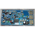
I need help with the test fm transmitter, "pll transmiter rdvv300"

Status
Not open for further replies.

Imalu3055

Member level 1
Joined
Dec 23, 2020
Messages
36
Helped
0
Reputation
0
Reaction score
0
Trophy points
6
Activity points
273
Hello!
Would someone be kind enough to tell me what is the method of setting the preset P1, in the "PLL transmiter rdvv300mW"?

It is not easy for me to get the BF980 FET, I could replace it with the 3N200, with the modifications for different pins, of course.
Thanks a lot
 

Attachments

  • Schematic RDVV300MW1a.pdf
    139.9 KB · Views: 200

P1 is used to adjust the Operating Point of BFR96S. Adjustment should be done so that C-Class Amplifier (BFR96S) reaches to wanted RF Power Output AND minimum Harmonic Contents.It's in fact not a very reliable method and it will shift the OP by temperature but anyway..
I cannot say that 3N200 may be replaced with BF980 because it acts as Oscillator and nobody can say 3N200 will absolutely work at its place.
Either it should be simulated or tried in its place..
 
Output stage is class C with P1 variable supply voltage respectively output power. Hopefully transistor maximum rating isn't exceeded in highest setting.

3N200 parameters are similar to BF980. I expect it's oscillating in this circuit.
 
Hello!
Thank you very much for the reply. I live in a rural area and we are building this station together with students from Rural School # 6 in Baradero. They are elementary school children, I do it with the purpose of guiding their future.
Unfortunately the setting of P1 would be optimal with a spectrum analyzer, I do not have. but we will solve it.
Is there a way to get the firmware of the PIC 16F628A in ASM? I am mounting the version of the FM test transmitter: https://bygselvhifi.dk/projects/fm-stereo-rds-transmitter/ The one with four switches below the display.

Attached file of the TSA5511 driver that we are using.

We are extremely grateful for your help !!!
 

Attachments

  • SchematicControlUnit3a.pdf
    81 KB · Views: 160

The schematic is looking too much complicated for what supposed to do the circuit.
I think will be hard to make it work properly, with so many weird approaches shown in the schematic.

Maybe is better to buy an already made circuit, which anyway has many more futures as: stereo line input, microphone input, USB input, DSP audio, digital volume, temperature compensated crystal reference, etc. And at $6, its price is unbeatable.

**broken link removed**

The components are shown clearly on the circuit, and their function can be presented for educational purposes.

If a national postal service is available, you will get the shipped package, wherever your place is located.
 

Hi. I understand your point of view, but the purpose of what we are doing is that the children learn and understand how each part works, we learn from mistakes. You cannot experiment with the module you propose.
 

I agree with vfone. The circuit is overly complex and not very instructive. The challenge is to make it work at all.

According to your description, you want to experiment with basic RF topics like oscillator, frequency tuning, modulation, power amplifier, antenna matching.

Having a cheap spectrum analyser tool (e.g. a 20 $ DVBT-STICK) would be much more important than a uC controlled PLL.
 
Very good idea!! It did not occur to me to use a DVBT-STICK. I have one and will use it. Thank you very much for your contribution! I would only need to obtain the firmware for PIC16F628A, used on the display board, in ASM format.
Thanks a lot.
 

Hello! I'm having RDVV malfunction. The version I assembled is: https://bygselvhifi.dk/projects/fm-...prettyPhoto[bigfmtransmitter-lex.europa.eu/5/. It has 5 buttons. I managed to start it, change the frequency but despite indicating "locked" it does not enable the voltage on T3 and T4 and there is no output power. Where can I get clear driving instructions? Its operation is erratic.
I measure voltage on pin 18 of the TSA5511 and it does not change when changing frequency.
The frequency measured on pin 15 of the TSA5511 is approximately 95MHz and no matter how deformed L7 does not change.
I am disappointed.
 

Attachments

  • Schematic RDVV300MW1a.pdf
    139.9 KB · Views: 126
  • SchematicControlUnit3a.pdf
    81 KB · Views: 128

Hello! Fixed issue, now it oscillates in frequency. Although a problem persists in the voltage cut-off circuit of the output stage: T3 always at cut-off even though the display indicates "LOCKED". Also when the power is cut it does not memorize the frequency, it returns to 87.5MHz. I insist: does anyone have information about the correct operation of the control? Thank you.
 

Attachments

  • SchematicControlUnit3a.pdf
    81 KB · Views: 135

T2 acts as a C-Class Power Amplifier so there shouldn't be any DC Current unless RF Signal is ON.Then when RF Signal arrives, a DC Current ( mean value ) will flow.Check P2(11) Enable is LOW or HIGH.. ( Normally it should be LOW)
 

Hi!
Regarding the firmware of the PIC16F84A or PIC16F628A of the TSA5511 controller. I have observed that there are many variants, but the circuit is similar. Some with 16x2 LCD display and others with 16x1. My question: Can I use any of the published firmware and will the TSA5511 behave the same way?
I purchased "FM loop phase-locked rdvv broadband notune pc board 87.5-108MHz 0-6W Broadcast (by moutoulos ™)"
Thank you!!!
 

Attachments

  • fm-pll-rdvv-pcb-broadband-notune-875-108mhz-0-5w-broadcast.jpg
    fm-pll-rdvv-pcb-broadband-notune-875-108mhz-0-5w-broadcast.jpg
    125.8 KB · Views: 144

Dear Vfone,

What an excellent answer! It solves all my doubts! (Ha!). I ask him a question: "If you meet Henry Ford, would you ask him if the cars he makes are good?

Do you know what RDVV means? Answer: "
Rani Durgavati Vishwavidyalaya, Jabalpur, India ". It is a prestigious university where the original project came from, to which dozens of fans made variations. NOBODY ANSWERS THE QUERY, even" https://bygselvhifi.dk/ "have blocked their mailbox. Now do you understand why my silly question?

I hope I have not inconvenienced you or the forum and if I did I apologize.

Thanks and if anyone knows the answer to whether all the firmware for the 16F84A or 16F628A that controls the TSA5511 are compatible, I appreciate it.
 

All right, now you enlightened my thoughts.
During many years working in this domain I made huge mistake when I contacted manufacturers as: Siemens, Infineon, Philips, NXP, Hewlett Packard, Keysight, Tektronix, Rohde & Schwarz, etc., to ask questions about their products. I should assume that all of them are serial liars, promoting their overrated products.
 

Thank you very much, but there are times when the filament of the lamp that illuminates us ... It burns.
Of course I have consulted the authors. No one answered and the site "https://bygselvhifi.dk/" cannot send emails.
Do you think that I like to bother the members of this forum in vain?
 

Thanks and if anyone knows the answer to whether all the firmware for the 16F84A or 16F628A that controls the TSA5511 are compatible
They have compatible pin layout and are the same code recompiled for the 16F628A (or 16F1827/16F1847) will work but the same binary firmware almost certainly won't work.

And there is no reason why the EEPROM in those devices can't store the last used frequency if the code is modified to do so.

Brian.
 

Status
Not open for further replies.

Part and Inventory Search

Welcome to EDABoard.com

Sponsor

Back
Top