D.A.(Tony)Stewart
Advanced Member level 7
- Joined
- Sep 26, 2007
- Messages
- 9,000
- Helped
- 1,823
- Reputation
- 3,645
- Reaction score
- 2,196
- Trophy points
- 1,413
- Location
- Richmond Hill, ON, Canada
- Activity points
- 59,529
From the number of unknowns transistor part number and no schematic, you need more experience to debug this.
I started a rough schematic using PSP7 (paint shop pro7) line up your pictures to flip the bottom and make the top partially transparent. then crudely trace the lines ( 15 min)
If you want to learn how to debug, get the transistor part numbers, maybe cap values then it might be possible to make a more readable schematic.
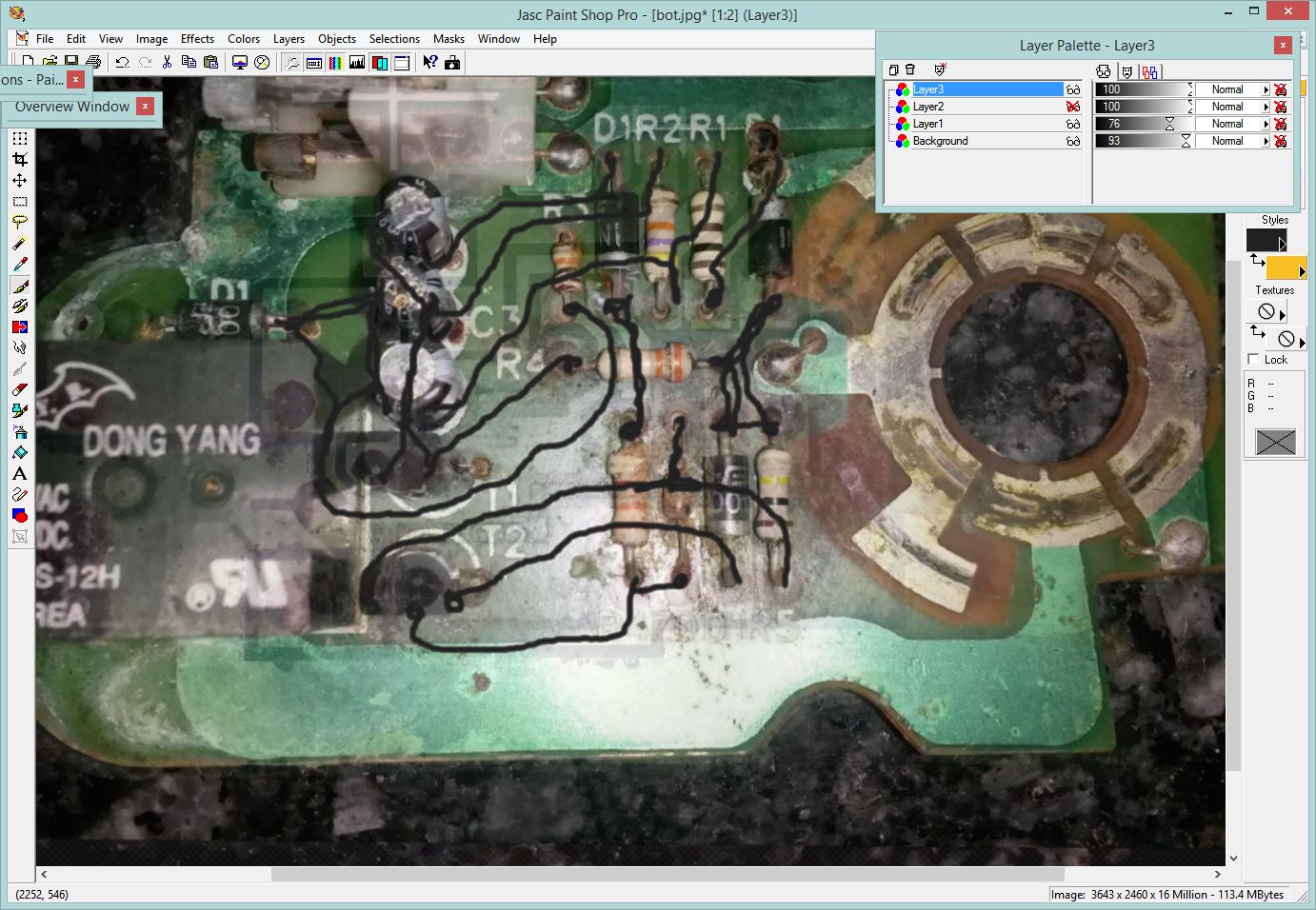
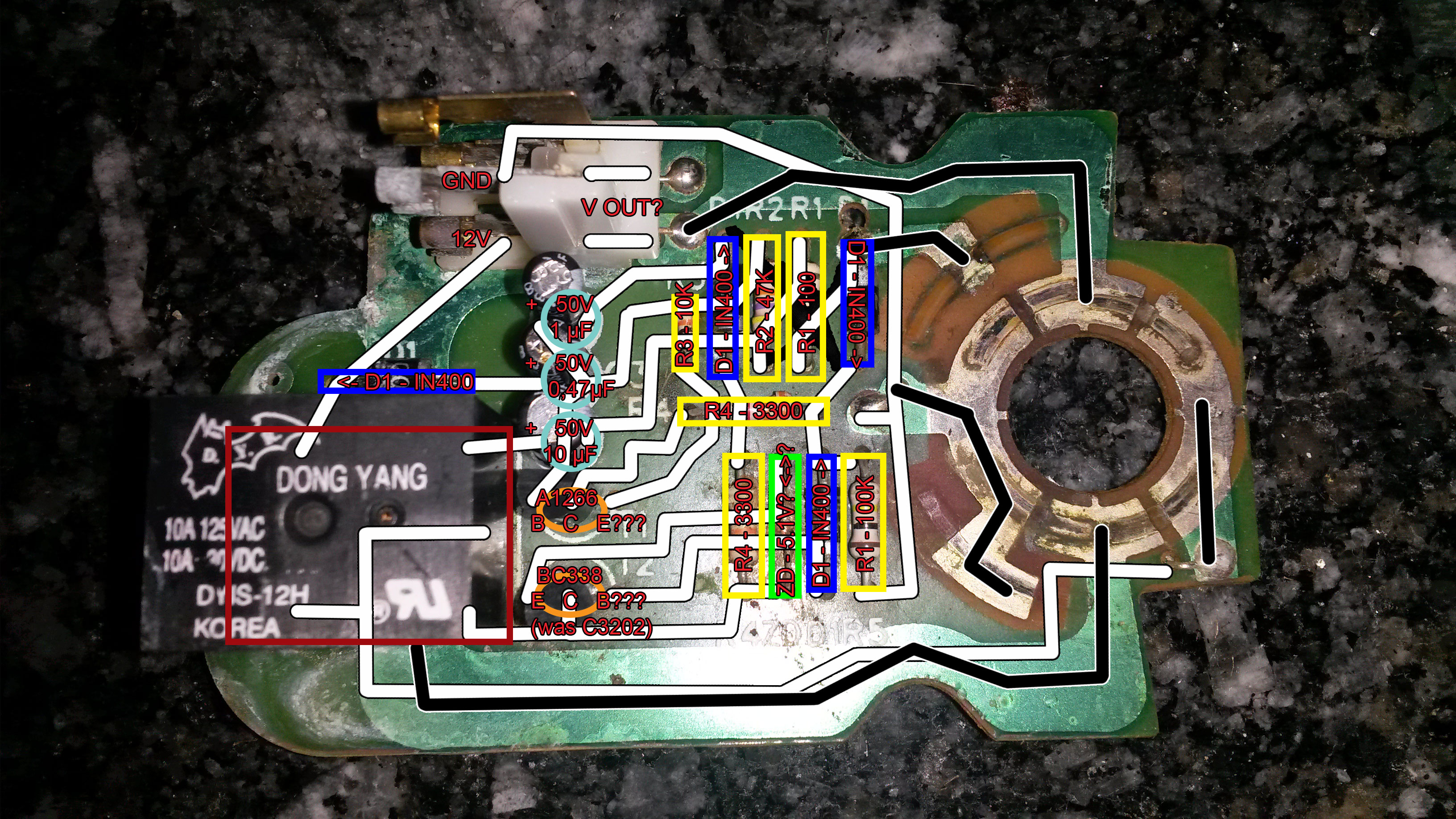
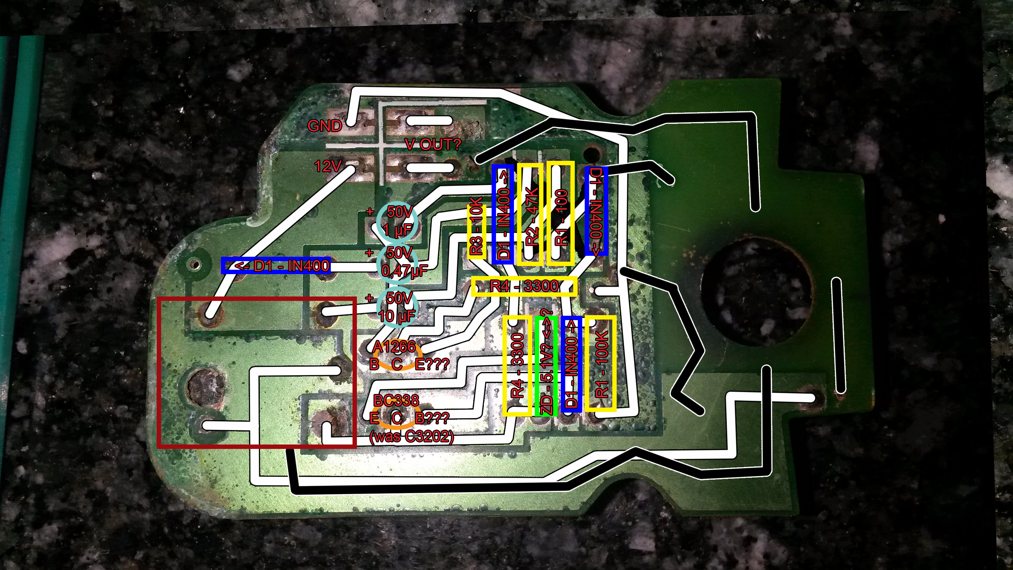
 I hope it is useful. The back side is flipped in order to fit the diagram. The white path is for the back side, and the black path is for the front side (I got lost when I reach the relay).