Continue to Site

Welcome to EDAboard.com

Welcome to our site! EDAboard.com is an international Electronics Discussion Forum focused on EDA software, circuits, schematics, books, theory, papers, asic, pld, 8051, DSP, Network, RF, Analog Design, PCB, Service Manuals... and a whole lot more! To participate you need to register. Registration is free. Click here to register now.

[SOLVED] Help with driving SCR with Microcontroller

Status
Not open for further replies.

JorgenK

Newbie level 3
Joined
Sep 17, 2014
Messages
3
Helped
0
Reputation
0
Reaction score
0
Trophy points
1
Location
Winnipeg, Canada
Activity points
31
Hello,

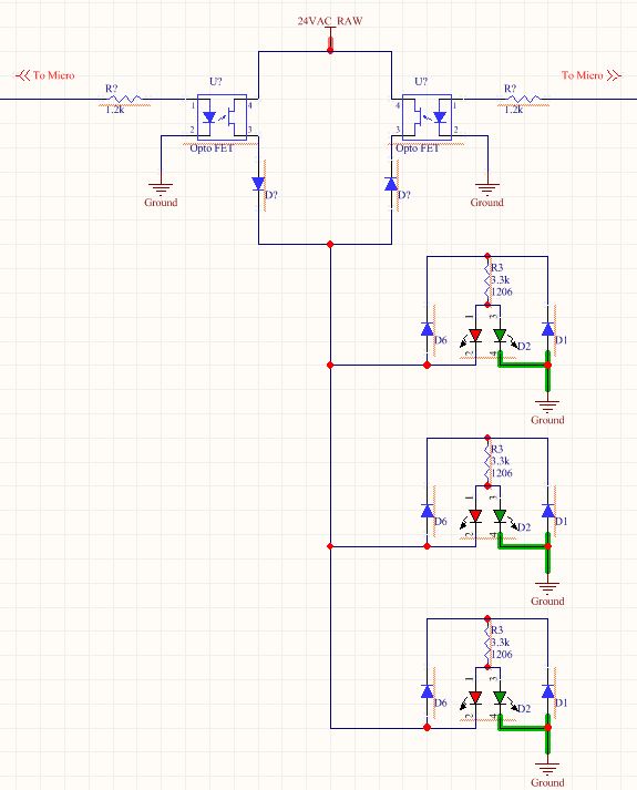
I am using SCR's to drive a red/green bi-color LED with a 24VAC signal. I am doing this so I can get four color states from one line (Red, Green, Yellow, Off).

scrcct.jpg

LEDcct.jpg

Anyway, I am wondering if this is the proper way to trigger the gate of the SCR with a microcontroller. The SCR I am using is a NXP BT168GW and a 3.3V PIC microcontroller. I realize I could use an opto-isolator, however board space is limited and I need 6 of these circuits on the board.

My main concern with this circuit is will the gate voltage will be properly referenced to the cathode of the SCR, to trigger the device?

Any help or comments would be greatly appreciated.

Thank you,
Jorgen
 

Hi,

really interesting how to drive a LED....

LED connections are OK, should work this way.

I can´t see how you want to drive the SCRs. What driver circuit or connection?

Additional effort is needed for the timing control. Zerocross detection hardware and software...

***********

What about using the LED, a current limiting resistor and two digital NPN BJTs (PDTCxxxx)?
And additionally for all six circuits a diode and a capacitor?

Makes 4 x 6 + 2 parts = 26 parts in total

With your solution it is 8 parts (shown) per circuit (missing SCR driver) plus zerocross detection ...
This makes at least 8 x 6 = 48+ parts

Klaus
 

Thank you for the reply and the suggestion Klaus,

The LED cct will be located on external boards and I will have up to 10 of them in parallel. I will have the driver circuit on a main controller board that all the external boards will plug into.

It seems the simplest way to do this is to just use the zero cross detection IC. I would like to use the MOC3063, is there any way to configure this to drive only one SCR or should I use a TRIAC and a diode?

Ideally I could use the TRIAC in the MOC6063, with an external diode to drive the LED cct, however the datasheet recommends I do not do this.

*******************

Also, i'm not sure I understand what you are suggesting with the transistors and capacitor.

Thanks again,
Jorgen
 

Hi,

Questions:
do you need brightness control?
Do you need isolation between 24V and uController?
***

The whole circuit is not clear to me.
To independently control the two leds you either need two MOCs and two SCRs with a lot of circuitry around
or one MOC and a triac plus software controlled triggering (halfwave dependent)..


****
If space is a concern then there may be much smaller solutions. It depends on the upper questions.

For me the simples way is to rectify the 24V AC and filter it with a C. Then you have DC.
If non-isolated: you only need a BJT to control the LEDs
If isolated: a PHOTOMOS (expensive) or a simple optocoupler would do.

Maybe you can show us a complete schematic.

Klaus
 

I do not need Brightness control, and I do not need isolation from 24VAC.

I am trying to send the signal over one conductor in a RJ45 cable and I want the four LED states, that is why I am using AC instead of DC. With AC I can do +ve half of wave for green, -ve half of wave for red, full wave for yellow and no wave for off.

I set up this circuit and the PNP switched fine but I was getting 24VAC on the base of the NPN.


Any idea why that would be?

I am starting to like the idea of using a PHOTOMOS. I set up this circuit this afternoon and everything seemed to work fine.


See any problems with it or anything I am forgetting?

Thank you,
Jorgen
 

Attachments

  • ledcircuit.jpg
    ledcircuit.jpg
    50.9 KB · Views: 110
  • moscct.jpg
    moscct.jpg
    54.2 KB · Views: 107

Hi,

now it´s getting clearer...

i always thought you want to control 6 (10) channels independently... sorry for that.

Now i see the two wire system. That´s OK.

*****
Hints:
* Maybe the photomos need some protection circuit (ESD)
* 24 V is a waste of power, but it seems to be no problem
* maybe it is possible to work with 5V and instead of sine shaped AC you could control it with a full bridge. But i´m not sure...

Good luck

Klaus
 

Status
Not open for further replies.

Similar threads

Part and Inventory Search

Welcome to EDABoard.com

Sponsor

Back
Top