Continue to Site

Welcome to EDAboard.com

Welcome to our site! EDAboard.com is an international Electronics Discussion Forum focused on EDA software, circuits, schematics, books, theory, papers, asic, pld, 8051, DSP, Network, RF, Analog Design, PCB, Service Manuals... and a whole lot more! To participate you need to register. Registration is free. Click here to register now.

Gain and amplitude of an LC oscillator with a non ideal OPAMP

Status
Not open for further replies.

d_sl4y3r

Newbie level 3
Joined
Oct 27, 2009
Messages
3
Helped
0
Reputation
0
Reaction score
0
Trophy points
1,281
Location
Portugal
Activity points
1,301
Gain and amplitude of a LC oscillator with a non ideal OPAMP

I'm studying for electronics, but I'm lost with this exercise.

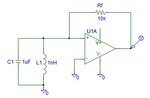
Consider the following oscillator in the picture.

The AMPOP is not ideal: Rin=1k, Rout=1.
How do I determine the minimal voltage gain Av in order for the circuit to function?

Also, the RMS current that feeds the AMPOP is 4mA.
Ignoring the small internal loss of the amplifier, how do I define the oscillation amplitude at the terminals of the LC section?
 

Attachments

  • lc_negimp.jpg
    lc_negimp.jpg
    8.2 KB · Views: 96
Last edited:

Re: Gain and amplitude of a LC oscillator with a non ideal OPAMP

The AMPOP is not ideal: Rin=1k, Rout=1.
That is a very bad opamp you have there. Replace it with a better one. Any realistic opamp have much higher input impedance than that.

How do I determine the minimal voltage gain Av in order for the circuit to function?
Long time ago I did such opamp calculations so I cant help, I'm afraid.
Byt, I do have a similar drawing here. There is one difference. On my drawing there is a potensiometer between output to ground, center pin to negative input (instead of directly to ground).
 

Re: Gain and amplitude of a LC oscillator with a non ideal OPAMP

Yes, it is really a poor quality OPAMP for this exercise.
I suppose the purpose is to is to understand the effect of the intrinsic "imperfection".

Also, I think the OPAMP here is implementing a negative impedance, to compensate for the energy loss of the LC circuit.
This because in reality the LC section behaves as C//L//R, and so the oscillation get smaller and smaller until all the energy has dissipated.

This is a theoretical problem, and I don't know how to solve this.
 

Status
Not open for further replies.

Part and Inventory Search

Welcome to EDABoard.com

Sponsor

Back
Top