Continue to Site

Welcome to EDAboard.com

Welcome to our site! EDAboard.com is an international Electronics Discussion Forum focused on EDA software, circuits, schematics, books, theory, papers, asic, pld, 8051, DSP, Network, RF, Analog Design, PCB, Service Manuals... and a whole lot more! To participate you need to register. Registration is free. Click here to register now.

FPGA Door Unlocker

Status
Not open for further replies.

versionDefect

Newbie
Joined
Apr 5, 2022
Messages
3
Helped
0
Reputation
0
Reaction score
0
Trophy points
1
Activity points
35
Hi all!

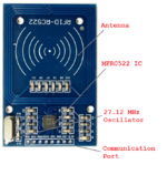
I am a Sophomore in college and have to make a final project with my FPGA board. The original idea was to unlock doors using RFID keycards but that seems pretty diffucult with FPGA, so instead I'm want to use a keypad that if a specific code is entered on a keypad to release the lock on the door (using a relay and the GPIO ports).

I know how to do this on a rasp pi and Arduino but how would or could I even do this on an FPGA board?
 

Write FPGA code that will:

1) Read the keypad
2) determine if the entered value is the correct "unlock" code
3) Drive your logic output high to energize the relay.

Without you having done anything, or asking specific questions, there's not much more help we can offer.
 

Hi,

just think as if you just have to use standard logic.

Draw a sketch, draw a schematic, draw a timing diagram, draw a flow chart...

***
BTW:
I don´t think that an RFID doorlock is that complicated.
For a couple of tags you may hard code them, for more tags use an external EEPROM.

Klaus
 

If you know Arduino then take a look at this page https://www.circuitstoday.com/interfacing-rfid-with-arduino and translate what the Arduino does to an FPGA hardware design.

Which looks to me like a UART interface to receive the RFID data, which you can then compare to what IDs you allow to open the lock. This is seems less complicated than the FSM you would have to write to monitor the keypad.
--- Updated ---

Here's a thought, use the RFID to enable the keypad for a 2 factor authentication door opener!
 

Without you having done anything, or asking specific questions, there's not much more help we can offer.
you are totally correct. Sorry.

The part that I am confused about is how to interpret the actual keypad or RFID signal into numbers.
We are using the Altera DE2 board. We have gone over a lot of the basic displays a number going up into hex And a car turn signal thing. Nothing too advanced.

The part I am struggling to understand is checking the data. In high-level code, you all probably know better than me that I could just throw a big if statement along the lines of if (ID = 15523) {unlockDoor();}. The part I am a bit confused about is interpreting the ID of the RFID Card.

How do I check the input in the FPGA board? I just want to know if this kind of project is achievable with my little knowledge in FPGA. As long as the FPGA can check the card and output a signal I could do the rest its just the fact that its an FPGA that I'm a bit worried on.

Here's a thought, use the RFID to enable the keypad for a 2 factor authentication door opener!
I thought this too but I have to submit what I am going to do and how exactly im going to do it in 2 days. Keypad into FPGA shouldn't be TOO difficult but even then we have never interfaced with external devices So I don't want to bite off more than what I could chew yk?
 

Hi
The part that I am confused about is how to interpret the actual keypad or RFID signal into numbers.
This is staright forward.
They just are a series of "0" and "1", so it´s rather clear: "11001"(binary) for example gives 0x19 or 25.

And yes, it`s just a big "IF". each bit of the received stream needs to match with the stored ID to open the door.
(but "IF" is more a software style. Don´t think as software. Think as "logic".
There are several ways in logic to check whether two bits are matching. One solution is an "XOR" logic. It´s output is "0" when both inputs are "matching")

As already written: An FPGA is just a bunch of logic (ICs) you can combine as you like.

--> Again: start with some drawings. Mainly not for us, but for yourself.

How do I check the input in the FPGA board?
An FPGA is digital logic. There are several ways to "check" the input.
Ask yourself: How does an AND gate check it´s inputs? Or how does a DFF check it´s inputs.
It´s the same with FPGAs.

Klaus
 
Hi again.

(but "IF" is more a software style. Don´t think as software. Think as "logic".
I hate to admit I do this very often lol.

I rigged everything up and it works (just using the 5V and 3.3V pins manually)! I'm considering exclusively doing it as RFID.

My school has these Arduino RFID readers (first attachment)

But I also see an AVR / Arduino kit version that seems a lot more straightforward. This one is just a serial input into the FPGA (along with power ofc).

If someone could just point me in the right direction or a similar example of someone doing this I would appreciate it.
 

Attachments

  • P25-02.png
    P25-02.png
    384 KB · Views: 98

Hi,

I miss some effort from your side.
No drawing, no flow chart, no trial...
Not even a clear question.

I think we gave you some hints, some approaches, some explanations ... without feedback.

Thus I recommend to show your idea, tell us what you understand so far, and where exactly you need help.

Klaus
 

Status
Not open for further replies.

Similar threads

Part and Inventory Search

Welcome to EDABoard.com

Sponsor

Back
Top